AD 2 AERODROMES
RKSI — Incheon INTL
RKSI AD 2.1 AERODROME LOCATION INDICATOR AND NAME
RKSI - SEOUL / Incheon INTL
RKSI AD 2.2 AERODROME GEOGRAPHICAL AND ADMINISTRATIVE DATA
| 1 |
ARP coordinates and site at AD |
372745N 1262621E 295° / 2 357 m from THR 33R |
|
2 |
Direction and distance from city |
264°, 48.7 km from Seoul City Hall 279°, 23.9 km from Incheon City Hall |
|
3 |
Elevation/Reference temperature |
7 m / 30.4 °C |
|
4 |
Geoid undulation at AD ELEV PSN |
21 m |
|
5 |
Magnetic VAR/Annual change |
9° W (2020) / 0.093° increasing |
|
6 |
Aerodrome Operator, Address, Telephone, FAX, AFS |
Incheon International Airport Corporation 47, Gonghang-ro 424beon-gil, Jung-gu, Incheon 22382, Republic of Korea TEL : +82-32-741-2601~2 FAX : +82-32-741-2610 AFS : (Terminal 1) RKSIZPZX (Terminal 2) RKSIZPZB |
|
7 |
Types of traffic permitted(IFR/VFR) |
IFR/VFR |
|
8 |
Remarks |
Incheon Airport Slot Coordination(IASC) Slots must be obtained prior to commencing operations at RKSI (Level-3 airport).
* For General/Business Aviation, submit GCR messages to obtain slot clearance. * Details of slot coordination procedures are outlined on the website (www.iasc.kr). |
RKSI AD 2.3 OPERATIONAL HOURS
|
1 |
Aerodrome Operator |
H24 |
|
2 |
Customs and Immigration |
H24 |
|
3 |
Health and Sanitation |
H24 |
|
4 |
AIS Briefing Office |
H24 |
|
5 |
ATS Reporting Office |
H24 |
|
6 |
MET Briefing Office |
H24 |
|
7 |
ATS |
H24 |
|
8 |
Fuelling |
H24 |
|
9 |
Handling |
H24 |
|
10 |
Security |
H24 |
|
11 |
De-icing |
H24 |
|
12 |
Remarks |
NIL |
RKSI AD 2.4 HANDLING SERVICES AND FACILITIES
|
1 |
Cargo handling facilities |
All modern facilities handling weights up to 7 000 kg |
|
2 |
Fuel/oil types |
Fuel : Jet A-1 Oil : Turbo Oil 2 380, Jet Oil 254, Castrol 5 000 Oil : Turbo Oil 2380, Jet Oil 254, Castrol 5000 |
|
3 |
Fuelling facilities/capacity |
|
|
4 |
De-icing facilities |
Provide 33 de-icing pads (Refer to Aircraft Parking / Docking Chart) |
|
5 |
Hangar space for visiting aircraft |
Not available |
|
6 |
Repair facilities for visiting aircraft |
Minor repairs without hangar |
|
7 |
Remarks |
NIL |
RKSI AD 2.5 PASSENGER FACILITIES
|
1 |
Hotels |
In Incheon & Seoul city (Transit hotel at passenger terminal) |
|
2 |
Restaurants |
At AD and in the city |
|
3 |
Transportation |
Rail, buses, taxis, rental cars and ferries from the AD |
|
4 |
Medical facilities |
|
|
5 |
Bank and Post Office |
Available at AD |
|
6 |
Tourist Office |
Available at AD |
|
7 |
Remarks |
http://airport.kr |
RKSI AD 2.6 RESCUE AND FIRE FIGHTING SERVICES
|
1 |
AD Category for fire fighting |
AD Category for fire fighting : Category 10 Category 10 | ||||||||||||||||||||||||||
|
2 |
Rescue equipment |
| ||||||||||||||||||||||||||
|
3 |
Capability for removal of disabled aircraft |
| ||||||||||||||||||||||||||
|
4 |
Remarks |
* ARFF (Aircraft Rescue and Fire-fighting) |
RKSI AD 2.7 SEASONAL AVAILABILITY-CLEARING
|
1 |
Type of clearing equipment |
|
|
2 |
Clearance priorities |
|
|
3 |
Remarks |
NIL |
RKSI AD 2.8 APRONS, TAXIWAYS AND CHECK LOCATIONS / POSITION DATA
|
1 |
Designation, Apron(Ramp) surface and strength |
|
|
2 |
Designation, Taxiway width, surface and strength |
Taxiway width, surface and strength:
|
|
3 |
Altimeter check location and elevation |
Every specified stands (Refer to aircraft Parking/Docking Chart) |
|
4 |
VOR check point |
See AD Chart |
|
5 |
INS check points |
INS Checkpoints : Every specified stand (Refer to aircraft Parking/Docking Chart) |
|
6 |
Remarks |
NIL |
RKSI AD 2.9 SURFACE MOVEMENT GUIDANCE AND CONTROL SYSTEM AND MARKINGS
|
1 |
Use of Mode S transponder on the ground | |
|
1.1 |
General |
This system using Mode S transponder improves the accuracy and the reliability of the ground movement monitoring system. |
|
1.2 |
ACFT equipped with Mode S transponder |
ACFT operators shall ensure that Mode S transponders are able to operate when ACFT is on the ground. |
|
1.2.1 |
Departing ACFT |
Prior to push-back or taxiing from a parking stand whichever comes first : - Enter, using either FMS mode or transponder control unit, the flight identification as specified in item 7 of the ICAO flight plan(ex.: KAL123, AAR456) or enter in the absence of flight identification, the ACFT registration. - Select XPNDR or its equivalent in relation to specifications on the installed model. - If function is available, select AUTO mode. - Do not select Off or SDBY functions. - Set Mode A code assigned by ATC. Lining up - Select TA/RA. |
|
Arriving ACFT |
After landing and until the ACFT is stationary at parking stand : - Maintain XPNDR or its equivalent in relation of specification of the installed model. - Do not select OFF and SDBY functions. - Maintain Mode A code assigned by ATC. When ACFT is stationary at the parking stand, select OFF or SDBY. | |
|
Other cases of taxiing ACFT |
- Select XPNDR or its equivalent in relation to specifications of the installed model. - If function is available, select AUTO mode. - Do not select the OFF and SDBY function. - Set Mode A code to 2000. | |
|
1.3 |
ACFT not equipped with Mode S transponder or with an unserviceable Mode S transponder |
Departing ACFT : - Maintain Mode A+C transponder in the ON position until lining up. Arriving ACFT : - Maintain Mode A+C transponder in the ON position and Mode A code assigned by ATC until parking stand. Other cases of taxiing ACFT : - Select A+C transponder in the ON position or its equivalent in relation to specifications of the installed model. - Do not select the OFF and SDBY function. - Set Mode A code to 2000. Fully parked on stand : - Select OFF or SDBY position. |
|
2 |
RWY and TWY marking and LGT |
|
|
3 |
Stop Bars and RWY Guard Lights |
|
|
4 |
Intermediate Holding Position Lights |
|
|
5 |
A-SMGCS & ASDE |
|
|
6 |
Remarks |
NIL |
|
General explanation of PDU(Pilot Display Unit) _ Concourse | |
 |
|
|
The VDGS(Visual Docking Guidance System) Docking Procedure _ Concourse | |
 |
1. The docking preparation After initializing the docking stand designation, the expected aircraft type and the stand number will be alternatively displayed on the upper LCD of the PDU. At the same time, the lead-in lights installed along the stand centre line will be switched on. 2. The azimuth guidance information When the aircraft is detected by the camera, azimuth guidance information will be provided on the lower LCD of the PDU. In case the aircraft deviates from the stand centre line, the arrow symbol will be displayed. |
 |
3. The remaining distance information
|
 | |
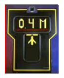 | |
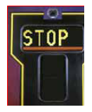 |
4. The Stop information
|
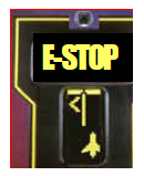 |
5. The ESTOP information
|
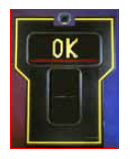 |
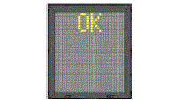
6. The docking completion information When the aircraft has reached the stop point within the tolerance, the OK message will be shown on the upper LCD of the PDU. |
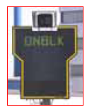 |
7. The ON BLOCK Information
|
 | |
|
A-CDM Information on VDGS _ Concourse | |
 |
TOBT or TSAT information is provided on VDGS for push-back waiting aircraft. (Refer to AD 2.20) |
 | |
|
Notice for the use of VDGS
| |
|
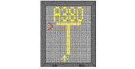
General explanation of PDU(Pilot Display Unit) _ Passenger Terminal #1 and #2 (#231~#243, #245~#268) | |
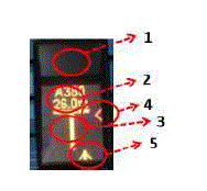 |
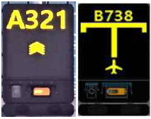
1.
It is the laser unit to detect the approaching aircraft.
2.
During the docking procedure, it visually represents the guidance information such as aircraft type and remaining distance.
3.
It represents the stand centre line. When the laser unit detects the approaching aircraft, this vertical bar is displayed to let the pilot know the correct course.
4.
It provides the azimuth guidance information to the pilot. When the aircraft deviates from the stand centre line, this symbol is shown to correct the direction which the arrow symbol points to.
5.
It is the symbol of the aircraft.
|
|
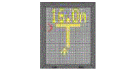
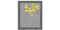
The VDGS(Visual Docking Guidance System) Docking Procedure _ Passenger Terminal #1 and #2 (#231~#243, #245~#268) | |
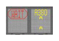 |
1.
The docking preparation
|
 |
2.
The azimuth guidance information
3.
The remaining distance information
|
 | |
 | |
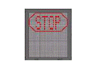 |
4.
The STOP information
|
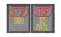 |
5.
The STOP_SBU/IDFAIL information
|
 |
6.
The docking completion information
When the aircraft has reached the stop point within the tolerance, the OK message will be shown on the upper LED of the PDU. |
 |
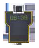
7.
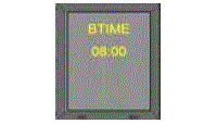
The BTIME(On Block time) Information
|
|
A-CDM Information on VDGS _ Passenger Terminal #1 and #2 (#231~#243, #245~#268) | |
 |
TOBT and TSAT information is provided on VDGS for push-back waiting aircraft. (Refer to AD 2.20) |
|
Notice for the use of VDGS 1.
VDGS service is provided to Passenger Terminal stands NR. 1(total 44). and NR. 2(total 51). Marshalling service
should be provided for any of the following cases;
2.
2.
In case the aircraft type displaying on the PDU is different from the actual approaching aircraft type, the pilot should
stop his aircraft immediately and notify the Incheon Apron, and then follow the marshaller's instruction.
3.
3.
If ID FAIL is displayed on the PDU between the stop point and 15 m prior to the stop point, the pilot should stop his
aircraft immediately and notify the Incheon Apron, and then follow the marshaller's instruction.
4.
If the ESTOP message is displayed on the PDU, the pilot should stop his aircraft immediately and notify the Incheon Apron, and then follow the marshaller's instruction. For any of the following cases, the field operator should press the emergency stop button.
5.
In case that the VDGS docking information and the marshaller's instruction are different, the pilot should follow the marshaller's instruction first.
6.
When the aircraft reaches about 10 m prior to the stop point, the pilot should decrease the speed as much as the aircraft could be stopped immediately until the STOP message is displayed on the PDU.
7.
If the aircraft approaches to the stand in excess of the speed limit, the SLOW message should be displayed on the PDU. The pilot should reduce the speed.
| |
|
General explanation of PDU(Pilot Display Unit) _ Cargo Terminal #1, #2 and Passenger Terminal #2 (#208∼#222, #224∼#225, #272~#291) | |
.png) |
1.
During the docking procedure, it visually represents the guidance information such as aircraft
type and remaining distance.
2.
It represents the stand centre line. When the laser unit detects the approaching aircraft, this
vertical bar is displayed to let the pilot know the correct course.
3.
It provides the azimuth guidance information to the pilot. When the aircraft deviates from the
stand centre line, this symbol is shown to correct the direction which the arrow symbol points to.
4.
It is the symbol of the aircraft.
5.
It is the laser until to detect the approaching aircraft.
|
|
The VDGS(Visual Docking Guidance System) Docking Procedure _ Cargo Terminal #1, #2 and Passenger Terminal #2 (#208∼#222, #224∼#225, #272~#291) | |
 |
1. The docking preparation
|
.png) |
2.
The azimuth guidance information
3.
The remaining distance information
|
.png) | |
.png) | |
.png) |
4.
The STOP information
|
.png) |
5.
The STOP SBU/ID-FAIL information
|
.png) |
6.
The docking completion information
When the aircraft has reached the stop point within the tolerance, the OK message will be shown on the upper LED of the PDU. |
.png) |
7.
The On block time information
|
|
A-CDM Information on VDGS _ Cargo Terminal and Passenger Terminal #2 (#208∼#222, #224∼#225, #272~#291) | |
.png) |
TOBT, TSAT and CTOT information is provided on VDGS for push-back waiting aircraft. |
|
Notice for the use of VDGS
| |
RKSI AD 2.10 AERODROME OBSTACLES
|
In Area 2 | |||||
|
OBST ID/Designation |
OBST type |
OBST position |
ELEV/HGT |
Markings/Type, colour |
Remarks |
|
a |
b |
c |
d |
e |
f |
|
RKSIOB001 |
Pylon |
373203.9N 1262255.8E |
428 ft/ |
Marked/LGTD |
In 33L/R, 15L/R, 16L/R, 34L/R APCH/TKOF |
|
RKSIOB002 |
Pylon |
373201.7N 1262345.5E |
389 ft/ |
Marked/LGTD |
In 33L/R, 15L/R APCH/TKOF |
|
RKSIOB003 |
Pylon |
373200.3N 1262417.0E |
358 ft/ |
Marked/LGTD | |
|
RKSIOB004 |
Pylon |
373200.1N 1262422.7E |
367 ft/ |
LGTD | |
|
RKSIOB005 |
Bridge |
372456.3N 1263345.7E |
788 ft/ |
LGTD | |
|
RKSIOB006 |
Bridge |
372442.7N 1263413.5E |
788 ft/ |
LGTD | |
|
RKSIOB007 |
Natural High Point |
373203.3N 1262056.5E |
512 ft/ |
NIL |
In 16L/R, 34L/R APCH/TKOF |
|
RKSIOB008 |
Pylon |
373212.4N 1262447.3E |
311 ft/ |
NIL |
In 33L/R, 15L/R, 16L/R, 34L/R circling area and at AD |
|
RKSIOB009 |
Natural High Point |
373143.3N 1262526.5E |
387 ft/ |
NIL | |
|
RKSIOB010 |
Natural High Point |
373129.2N 1262644.6E |
621 ft/ |
NIL | |
|
RKSIOB011 |
Antenna |
372720.8N 1262850.9E |
254 ft/ |
Marked/LGTD | |
|
RKSIOB012 |
Antenna |
372716.6N 1262855.0E |
251 ft/ |
LGTD | |
|
RKSIOB013 |
Natural High Point |
372427.5N 1262435.6E |
444 ft/ |
NIL | |
|
RKSIOB014 |
Pylon |
372503.6N 1262454.7E |
263 ft/ |
Marked/LGTD | |
|
RKSIOB015 |
Natural High Point |
372556.7N 1262524.7E |
245 ft/ |
NIL | |
|
RKSIOB016 |
Natural High Point |
372712.2N 1262406.6E |
274 ft/ |
NIL | |
|
RKSIOB017 |
Natural High Point |
372703.3N 1262443.8E |
267 ft/ |
NIL | |
|
RKSIOB018 |
Antenna |
372800.2N 1262142.2E |
598 ft/ |
LGTD | |
|
RKSIOB019 |
Building |
372649.9N 1262709.8E |
170 ft/ |
NIL | |
|
RKSIOB020 |
Antenna |
372936.0N 1263057.8E |
853 ft/ |
NIL | |
|
RKSIOB021 |
Antenna |
372240.9N 1262518.7E |
818 ft/ |
NIL | |
|
In Area 3 | |||||
|
OBST ID/ Designation |
OBST type |
OBST position |
ELEV/HG T |
Markings/Type, colour |
Remarks |
|
a |
b |
c |
d |
e |
f |
|
RKSIOB022 |
Tower |
372739.3N 1262625.9E |
345.9 ft/ |
LGTD |
In 33L/R, 15L/R, 16L/R, 34L/R APCH/TKOF |
|
RKSIOB023 |
Tower |
372722.9N 1262640.4E |
229.6 ft/ |
LGTD | |
|
RKSIOB024 |
Tower |
372759.9N 1262607.5E |
336.5 ft/ |
LGTD | |
RKSI AD 2.11 METEOROLOGICAL INFORMATION PROVIDED
|
1 |
Associated MET Office |
Aviation Meteorological Agency · TEL : +82-32-222-3030 · FAX : +82-32-740-2817 |
|
2 |
Hours of service MET Office outside hours |
24 hours - |
|
3 |
Office responsible for TAF preparation Periods of validity |
Aviation Meteorological Agency 30 hours at 0000, 0600, 1200, 1800 UTC |
|
4 |
Trend forecast Interval of issuance |
Trend Type forecast 30 minute(METAR) |
|
5 |
Briefing/consultation provided |
Available by the phone for 24 hours Available at the Office for 24 hours, if required |
|
6 |
Flight documentation language(s) used |
Aerodrome forecasts (TAF code form), SIGWX charts, WINTEM charts, SIGMET information in English |
|
7 |
Charts and other information available for briefing or consultation |
Analysis charts(surface and upper air), Prognostic charts, Graphic displays, Significant weather charts(high, medium, low) and other model outputs |
|
8 |
Supplementary equipment available for providing information |
Satellite and Terminal Doppler Weather radar imageries, Low Level Windshear Alert System |
|
9 |
ATS units provided with information |
FIC, TWR, APP and ACC |
|
10 |
Additional information (limitation of service, etc.) |
All observation data, model outputs and forecasts produced by KMA and WAFS are available at the office through Internet link. |
RKSI AD 2.12 RUNWAY PHYSICAL CHARACTERISTICS
|
Designations RWY NR |
TRUE BRG |
Dimension of RWY(m) |
Strength(PCR) and surface of RWY and SWY |
THR coordinates RWY end coordinates THR geoid undulation |
THR elevation and highest elevation of TDZ of precision APP RWY |
|---|---|---|---|---|---|
|
1 |
2 |
3 |
4 |
5 |
6 |
|
15L |
144.66° |
3750 × 60 |
|
372902.20N 1262624.56E GUND 21.5 m |
THR 6.9 m / 22.6 ft TDZ 6.9 m / 22.6 ft |
|
33R |
324.67° |
3750 × 60 |
|
372722.97N 1262752.82E GUND 21.5 m |
THR 6.9 m / 22.6 ft TDZ 6.9 m / 22.6 ft |
|
15R |
144.66° |
3750 × 60 |
|
372854.44N 1262610.82E GUND 21.4 m |
THR 6.9 m / 22.6 ft TDZ 6.9 m / 22.6 ft |
|
33L |
324.67° |
3750 × 60 |
|
372715.21N 1262739.08E GUND 21.5 m |
THR 6.9 m / 22.6 ft TDZ 6.9 m / 22.6 ft |
|
16L |
144.66° |
4000 × 60 |
|
372822.11N 1262456.06E GUND 21.3 m |
THR 7.0 m / 22.9 ft TDZ 7.0 m / 22.9 ft |
|
34R |
324.67° |
4000 × 60 |
|
372636.29N 1262630.22E GUND 21.5 m |
THR 7.0 m / 22.9 ft TDZ 7.0 m / 22.9 ft |
|
16R |
144.66° |
3 750 × 60 |
|
372807.71N 1262448.18E GUND 21.8 m |
THR 7.0 m / 22.9 ft TDZ 7.0 m / 22.9 ft |
|
34L |
324.67° |
3 750 × 60 |
|
372628.50N 1262616.45E GUND 21.9 m |
THR 7.0 m / 22.9 ft TDZ 7.0 m / 22.9 ft |
|
Remarks Geoid undulations of 16R and 34L are surveyed on the basis of national geoid model, KNGeoid18. | |||||
|
7. Slope of RWY-SWY | |||||
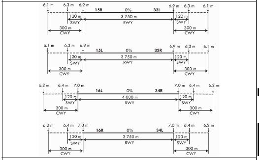 | |||||
|
SWY dimensions(m) |
CWY dimensions(m) |
Strip dimensions(m) |
RESA dimensions(m) |
Location &
description of arresting system |
OFZ |
Remarks | |
|---|---|---|---|---|---|---|---|
|
8 |
9 |
10 | 11 | 12 |
13 |
14 | |
|
120 × 60 120 × 60 |
300 × 150 300 × 150 |
4 110 × 300 |
240 × 150 240 × 150 |
NIL |
Conforms to the standards specified in Annex 14, Chapter 4 |
The surface of RWY 15R/33L, 15L/33R, 16L /34R, 16R/34L and Rapid exit taxiways are grooved. | |
|
120 × 60 120 × 60 |
300 × 150 300 × 150 |
4 110 × 300 |
240 × 150 240 × 150 |
NIL | |||
|
120 × 60 120 × 60 |
300 × 150 300 × 150 |
4 360 x 300 |
240 × 150 240 × 150 |
NIL | |||
|
120 × 60 120 × 60 |
300 × 150 300 × 150 |
4 110 × 300 |
240 × 150 240 × 150 |
NIL | |||
|
※ Scheduled Preventive Maintenance Time
| |||||||
RKSI AD 2.13 DECLARED DISTANCES
|
RWY Designator |
TORA (m) |
TODA (m) |
ASDA (m) |
LDA (m) |
Remarks |
|---|---|---|---|---|---|
|
1 |
2 |
3 |
4 |
5 |
6 |
|
15R |
3 750 |
4 050 |
3 870 |
3 750 |
NIL |
|
15R |
3 560 |
3 860 |
3 680 |
- |
Take-off from intersection at TWY B6* |
|
15R |
3 000 |
3 300 |
3 120 |
- |
Take-off from intersection with TWY K* |
|
15R |
2 550 |
2 850 |
2 670 |
- |
Take-off from intersection at TWY B5 |
|
15R |
2 250 |
2 550 |
2 370 |
- |
Take-off from intersection at TWY B4 |
|
15R |
2 460 |
2 760 |
2 580 | - |
Take-off from intersection at TWY C8 |
|
33L |
3 750 |
4 050 |
3 870 |
3 750 |
NIL |
|
33L |
3 560 |
3 860 |
3 680 |
- |
Take-off from intersection at TWY B1* |
|
33L |
3 000 |
3 300 |
3 120 |
- |
Take-off from intersection with TWY J* |
|
33L |
2 550 |
2 850 |
2 670 |
- |
Take-off from intersection at TWY B2 |
|
33L |
2 250 |
2 550 |
2 370 |
- |
Take-off from intersection at TWY B3 |
|
33L |
2 520 |
2 820 |
2 640 |
Take-off from intersection at TWY C3 | |
|
15L |
3 750 |
4 050 |
3 870 |
3 750 |
NIL |
|
15L |
3 000 |
3 300 |
3 120 |
- |
Take-off from intersection with TWY K* |
|
15L |
2 550 |
2 850 |
2 670 |
- |
Take-off from intersection with TWY D6** |
|
33R |
3 750 |
4 050 |
3 870 |
3 750 |
NIL |
|
33R |
3 000 |
3 300 |
3 120 |
- |
Take-off from intersection with TWY J* |
|
33R |
2 550 |
2 850 |
2 670 |
- |
Take-off from intersection at TWY D1 |
|
16L |
4 000 |
4 300 |
4 120 |
4 000 |
NIL |
|
16L |
3 810 |
4 110 |
3 930 |
- |
Take-off from intersection at TWY N6* |
|
16L |
3 314 |
3 614 |
3 434 |
- |
Take-off from intersection with TWY V* |
|
16L |
3 009 |
3 309 |
3 129 |
- |
Take-off from intersection with TWY U* |
|
16L |
2 550 |
2 850 |
2 670 |
- |
Take-off from intersection at TWY N5 |
|
16L |
2 404 |
2 704 |
2 524 |
- |
Take-off from intersection at TWY P9 |
|
16L |
2 050 |
2 350 |
2 170 |
- |
Take-off from intersection at TWY N4 |
|
16L |
1 799 |
2 099 |
1 919 |
- |
Take-off from intersection at TWY W |
|
34R |
4 000 |
4 300 |
4 120 |
4 000 |
NIL |
|
34R |
3 810 |
4 110 |
3 930 |
- |
Take-off from intersection at TWY N1* |
|
34R |
3 259 |
3 559 |
3 379 |
- |
Take-off from intersection with TWY T* |
|
34R |
2 786 |
3 086 |
2 906 |
- |
Take-off from intersection at TWY P3 |
|
34R |
2 550 |
2 850 |
2 670 |
- |
Take-off from intersection at TWY N2 |
|
34R |
2 049 |
2 349 |
2 169 |
- |
Take-off from intersection at TWY N3 |
|
34R |
2 049 |
2 349 |
2 169 |
- |
Take-off from intersection at TWY W |
|
16R |
3 750 |
4 050 |
3 870 |
3 750 |
NIL |
|
16R |
3 555 |
3 855 |
3 675 |
- |
Take-off from intersection at TWY P12* |
|
16R |
3 314 |
3 614 |
3 434 |
- |
Take-off from intersection at TWY V* |
|
16R |
3 009 |
3 309 |
3 129 |
- |
Take-off from intersection at TWY U* |
|
16R |
2 500 |
2 800 |
2 620 |
- |
Take-off from intersection at TWY P11 |
|
16R |
2 200 |
2 500 |
2 320 |
- |
Take-off from intersection at TWY P10 |
|
16R |
1 900 |
2 200 |
2 020 |
- |
Take-off from intersection at TWY P8 |
|
16R |
1 600 |
1 900 |
1 720 |
- |
Take-off from intersection at TWY P7 |
|
16R |
1 875 |
2 175 |
1 995 |
- |
Take-off from intersection at TWY W |
|
34L |
3 750 |
4 050 |
3 870 |
3 750 |
NIL |
|
34L |
3 555 |
3 855 |
3 675 |
- |
Take-off from intersection at TWY P1* |
|
34L |
3 009 |
3 309 |
3 129 |
- |
Take-off from intersection at TWY T* |
|
34L |
2 500 |
2 800 |
2 620 |
- |
Take-off from intersection at TWY P2 |
|
34L |
2 200 |
2 500 |
2 320 |
- |
Take-off from intersection at TWY P4 |
|
34L |
1 900 |
2 200 |
2 020 |
- |
Take-off from intersection at TWY P5 |
|
34L |
1 600 |
1 900 |
1 720 |
- |
Take-off from intersection at TWY P6 |
|
34L |
1 875 |
2 175 |
1 995 |
- |
Take-off from intersection at TWY W |
* Entry Point for Intersection departure.
Note: Intersection departure may be initated by pilot or ATC and aproved by ATC considering trafic and en-route separation. ATC may change departure sequency for the purposes of trafic flow management.
RKSI AD 2.14 APPROACH AND RUNWAY LIGHTING
|
RWY Designator |
APCH LGT type LEN INTST |
THR LGT Color WBAR |
VASIS (MEHT) PAPI |
TDZ LGT LEN |
RWY Center Line LGT LEN, Spacing, Color, INTST |
RWY edge LGT LEN, Spacing Color, INTST |
RWY End LGT Color WBAR |
SWY LGT LEN(m) Color |
|---|---|---|---|---|---|---|---|---|
|
1 |
2 |
3 |
4 |
5 |
6 |
7 |
8 |
9 |
|
15R |
ALSF-II 900 m LIH |
Green Green |
PAPI Left / 3° (64.64 ft) |
900 m |
3 750 m 15 m white/Red LIH |
3 750 m 60 m white/Yellow LIH |
Red - |
120 m Red |
|
33L |
ALSF-II 900 m LIH |
Green Green |
PAPI Left / 3 ° (64.64 ft) |
900 m |
3 750 m 15 m white/Red LIH |
3 750 m 60 m white/Yellow LIH |
Red - |
120 m Red |
|
15L |
ALSF-II 900 m LIH |
Green Green |
PAPI Left / 3° (64.64 t) |
900 m |
3 750 m 15 m white/Red LIH |
3 750 m 60 m white/Yellow LIH |
Red - |
120 m Red |
|
33R |
ALSF-II 900 m LIH |
Green Green |
PAPI Left / 3° (64.64 ft) |
900 m |
3 750 m 15 m white/Red LIH |
3 750 m 60 m white/Yellow LIH |
Red - |
120 m Red |
|
16L |
ALSF-II 900 m LIH |
Green Green |
PAPI Left / 3° ( 67.14 ft) |
900 m |
4 000 m 15 m white/Red LIH |
4 000 m 60 m white/Yellow LIH |
Red - |
120 m Red |
|
34R |
ALSF-II 900 m LIH |
Green Green |
PAPI Left / 3° (67.14 ft) |
900 m |
4 000 m 15 m white/Red LIH |
4 000 m 60 m white/Yellow LIH |
Red - |
120 m Red |
|
16R |
ALSF-II 900 m LIH |
Green Green |
PAPI Left / 3° (67.14 ft) |
900 m |
3 750 m 15 m white/Red LIH |
3 750 m 60 m white/Yellow LIH |
Red - |
120 m Red |
|
34L |
ALSF-II 900 m LIH |
Green Green |
PAPI Left / 3° (67.14 ft) |
900 m |
3 750 m 15 m white/Red LIH |
3 750 m 60 m white/Yellow LIH |
Red - |
120 m Red |
|
10. Remarks: Road holding position lights are installed at all road entrances to the RWY 15L/33R, 15R/33L, 16R/34L. Lights of Golf course are installed at 1.6 km (750 m width × 500 m length) away from end of RWY 15R. | ||||||||
RKSI AD 2.15 OTHER LIGHTING, SECONDARY POWER SUPPLY
|
1 |
ABN/IBN location, characteristics and hours of operation |
ABN : At the top of main electrical substation, FLG W/G EV 2 SEC IBN : NIL H24 |
|
2 |
LDI location and lighting Anemometer location and lighting |
NIL Anemometer : 300 m from THR 15L/33R, 15R/33L, 16L/34R, 16R/34L and Run-up Area and Lighted |
|
3 |
TWY edge and center line lighting |
Edge : All TWY Curve area Centre line : All TWY |
|
4 |
Secondary power supply/switch-over time |
Secondary power supply to all lighting at AD Switch-over time: 1 SEC or 15 SEC |
|
5 |
Remarks |
Medium intensity obstacle light(white) at TWR is being operated by day. |
RKSI AD 2.16 HELICOPTER LANDING AREA
|
1 |
Coordinates TLOF or THR of FATO Geoid undulation |
H : 372744.42N 1262854.15E |
|
2 |
TLOF and/or FATO elevation m/ft |
H : 5.407 m (17.74 ft) |
|
3 |
TLOF and FATO area dimesions, surface, strength and marking |
H : Rectangle 25.1 x 25.1 m, Concrete PCN 16/R/B/X/T, white edges and white letter H. |
|
4 |
True BRG of FATO |
H : 145/325° GEO, 152/332° MAG Direction of TLOF zones : 145° GEO, 152° MAG 325° GEO, 332° MAG |
|
5 |
Declared distance available |
NIL |
|
6 |
APP and FATO lighting |
NIL |
|
7 |
Remarks |
1 day PPR from Incheon Airport AIS. Daytime only (VFR and special VFR condition) |
RKSI AD 2.17 ATS AIRSPACE
|
1 |
Designation and lateral limit |
Incheon CTR A circle, radius 5 NM centered at ARP. |
|
2 |
Vertical limits |
SFC to 3 000 ft AGL |
|
3 |
Airspace classification |
B |
|
4 |
ATS unit call sign Languages |
Incheon Tower English / Korean |
|
5 |
Transition altitude |
14 000 ft AMSL |
|
6 |
Operational hours |
H24 |
|
7 |
Remarks |
NIL |
RKSI AD 2.18 ATS COMMUNICATION FACILITIES
|
Service designation |
Call sign |
Frequency |
Hours of operation |
Remarks |
|---|---|---|---|---|
|
1 |
2 |
3 |
4 |
5 |
|
TWR |
Incheon Tower |
118.2 MHz(E) 118.8 MHz(W) 118.275 MHz(BK-FREQ) 231.8 MHz |
H24 |
EAST(E): RWY 15L/R, 33L/R operation WEST(W): RWY 16L/R, 34L/R operation |
|
GND |
Incheon Ground |
121.75 MHz(E) 121.7 MHz(W) 121.875 MHz(BK-FREQ) 121.925 MHz(BK-FREQ) 226.9 MHz |
H24 |
EAST(E): RWY 15L/R, 33L/R operation WEST(W): RWY 16L/R, 34L/R operation |
|
Apron |
Incheon Apron |
121.65 MHz 121.8 MHz 122.175 MHz 122.225 MHz 122.325 MHz 123.325 MHz 123.575 MHz 123.675 MHz 129.725 MHz |
H24 |
When de-icing, refer to RKSI AD 2-23 (De-icing operational procedures) |
|
DLVRY |
Incheon Delivery |
121.6 MHz(PRIMARY) 121.875 MHz(BK-FREQ) 269.2 MHz |
H24 |
Digital PDC service available |
|
ATIS |
Incheon INTL Airport |
ARR : 128.4 MHz 230.25 MHz DEP : 128.65 MHz 344.2 MHz BK-FREQ : 128.2MHz |
H24 |
1. Digital ATIS service available 2. 128.2 MHz used when 128.4 MHz, 128.65 MHz are not available 3. ATIS telephone service available. (Refer to RKSI AD 2-42 for detail) |
|
APP |
Seoul Approach |
119.75 MHz 119.1 MHz 124.7 MHz 120.8 MHz 121.35 MHz 119.05 MHz 124.2 MHz 293.3 MHz |
H24 | |
|
DEP |
Seoul Departure |
121.4 MHz 124.8 MHz 125.15 MHz 353.2 MHz |
H24 | |
|
VFR |
123.8 MHz 305.7 MHz 123.25 MHz 363.8 MHz |
H24 | ||
|
EMERG |
121.5 MHz 243.0 MHz |
H24 |
RKSI AD 2.19 RADIO NAVIGATION AND LANDING AIDS
|
Type of aid, MAG VAR, Type of supported OPS |
ID |
Frequency |
Hours of operation |
Position of transmitting antenna coordinates |
Elevation of DME transmitting antenna |
Remarks |
|---|---|---|---|---|---|---|
|
1 |
2 |
3 |
4 |
5 |
6 |
7 |
|
VOR/DME (9° W/2020) |
NCN |
113.80 MHz (CH 85X) |
H24 |
372941.7N 1262549.2E | 30 m |
Coverage 25 NM from NCN VOR with the following restrictions : VOR/DME unusable :
DME unusable :
Scheduled Inspection time : Every 4th, 14th day (1500-1900 UTC) of the month |
|
WNG |
112.900 MHz (CH 76X) |
H24 |
372558.6N 1262700.0E |
0 m |
Coverage 25 NM from WNG TVOR with the following restrictions : VOR/DME unusable :
DME unusable :
Scheduled Inspection time : Every 6th, 15th day (1500-1900 UTC) of the month | |
|
LOC 15R (9° W/2020) ILS CAT III (9° W or 351°) |
ISRR |
109.10 MHz |
H24 |
372707.4N 1262746.0E |
LOC unusable : LOC unusable beyond 15 NM from LOC due to RK P518 GP : 3° | |
|
DME 15R |
ISRR |
989 MHz (CH 28X) |
H24 |
372848.7N 1262621.9E |
0 m | |
|
GP 15R |
- |
331.4 MHz |
H24 |
372848.7N 1262622.0E | ||
|
IM 15R |
- |
75 MHz |
H24 |
372902.7N 1262603.5E | ||
|
MM 15R |
- |
75 MHz |
H24 |
372922.2N 1262546.1E | ||
|
LOC 33L (9° W/2020) ILS CAT III (9° W or 351°) |
INLL |
109.30 MHz |
H24 |
372902.2N 1262603.9E |
GP : 3° | |
|
DME 33L |
INLL |
991 MHz (CH 30X) |
H24 |
372725.4N 1262735.9E |
0 m | |
|
GP 33L |
- |
332.0 MHz |
H24 |
372725.5N 1262736.0E | ||
|
IM 33L |
- |
75 MHz |
H24 |
372706.9N 1262746.4E | ||
|
MM 33L |
- |
75 MHz |
H24 |
372647.4N 1262803.8E | ||
|
LOC 15L (9° W/2020) ILS CAT III (9° W or 351°) |
ISLL |
111.90 MHz |
H24 |
372715.1N 1262759.7E |
LOC unusable : LOC unusable beyond 15NM from LOC due to RK P518 GP : 3° | |
|
DME 15L |
ISLL |
1017 MHz (CH 56X) |
H24 |
372856.4N 1262635.7E |
0 m | |
|
GP 15L |
- |
331.1 MHz |
H24 |
372856.5N 1262635.7E | ||
|
IM 15L |
- |
75 MHz |
H24 |
372910.4N 1262617.2E | ||
|
MM 15L |
- |
75 MHz |
H24 |
372930.0N 1262559.8E | ||
|
LOC 33R ILS CAT III |
INRR |
108.90 MHz |
H24 |
372910.0N 1262617.6E |
GP : 3° | |
|
DME 33R |
INRR |
987 MHz (CH 26X) |
H24 |
372733.2N 1262749.7E |
0 m | |
|
GP 33R |
- |
329.3 MHz |
H24 |
372733.2N 1262749.8E | ||
|
IM 33R |
- |
75 MHz |
H24 |
372714.7N 1262800.2E | ||
|
MM 33R |
- |
75 MHz |
H24 |
372655.2N 1262817.5E | ||
|
LOC 16L (9° W/2020) ILS CAT III (9° W or 351°) |
IRKS |
110.35 MHz (CH 40Y) |
H24 |
372628.5N 1262637.1E |
LOC unusable : beyond 15NM from LOC due to RK P518 GP : 3° If unable to use "CH 40Y" FREQ., notify ATC ASAP | |
|
DME 16L |
IRKS |
1127 MHz (CH 40Y) |
H24 |
372811.4N 1262459.7E |
0 m | |
|
GP 16L |
- |
334.850 MHz |
H24 |
372811.3N 1262459.5E | ||
|
IM 16L |
- |
75 MHz |
H24 |
372830.3N 1262448.7E | ||
|
MM 16L |
- |
75 MHz |
H24 |
372849.9N 1262431.3E | ||
|
LOC 34R (9° W/2020) ILS CAT III (9° W or 351°) |
IRKN |
108.10 MHz |
H24 |
372829.9N 1262449.1E |
GP : 3° Caution advised when approaching Incheon AP ILS RWY 34R as follow : 1. False course captures may occur when approaching Incheon AP ILS RWY 34R, in the vicinity of 4 DEG clockwise 12 DEG AZM FM the published localizer course. 2. It is recommended for the pilot to : - Be aware of when the raw data indicates that the aircraft is approaching and establishing on the correct course ; and - Be aware that, should a false capture occur, it may be necessary to deselect and Re-Arm the approach mode in order to achieve a successful coupled approach on the correct localizer course | |
|
DME 34R |
IRKN |
979 MHz (CH 18X) |
H24 |
372642.5N 1262618.8E |
0 m | |
|
GP 34R |
- |
334.7 MHz |
H24 |
372642.4N 1262618.6E | ||
|
IM 34R |
- |
75 MHz |
H24 |
372628.0N 1262637.5E | ||
|
MM 34R |
- |
75 MHz |
H24 |
372608.5N 1262654.9E | ||
|
LOC 16R (9°W/2020) ILS CAT III (9°W or 351°) |
IRFS |
108.55 MHz |
H24 |
372620.6N 1262623.4E |
LOC unusable : beyond 15 NM from LOC due to RK P518 GP : 3° | |
|
DME 16R |
IRFS |
1109MHz (CH 22Y) |
H24 |
372757.0N 1262451.7E |
0 m | |
|
GP 16R |
- |
329.75 MHz |
H24 |
372756.9N 1262451.6E | ||
|
IM 16R |
- |
75 MHz |
H24 |
372816.0N 1262440.7E | ||
|
MM 16R |
- |
75 MHz |
H24 |
372835.4N 1262423.4E | ||
|
LOC 34L (9° W/2020) ILS CAT III (9° W or 351°) |
IRFN |
109.95 MHz |
H24 |
372815.5N 1262441.1E |
GP : 3° | |
|
DME 34L |
IRFN |
1123 MHz (CH 36Y) |
H24 |
372634.7N 1262604.9E |
0 m | |
|
GP 34L |
- |
333.65 MHz |
H24 |
372634.6N 1262604.8E | ||
|
IM 34L |
- |
75 MHz |
H24 |
372620.1N 1262623.8E | ||
|
MM 34L |
- |
75 MHz |
H24 |
372600.7N 1262641.1E | ||
|
Scheduled Inspection time: ㅇ ILS - 16R/34L : Every 3 days from the 1st day of the month(1500-1900 UTC) (for example May 1, 4, 7, 10... etc.) - 15R/33L and 15L/33R : Every 3 days from the 2nd day of the month(1500-1900 UTC) (for example May 2, 5, 8, 11... etc.) - 16L/34R : Every 3 days from the 3rd day of the month(1500-1900 UTC) (for example May 3, 6, 9, 12... etc.) ※ ILS is unserviceable during the scheduled inspection time. ※ A 30 minutes prior request is required to use ILS . ㅇ RADAR(PSR, SSR, ARTS) : Every 1st, 2nd and 3rd THU (1500-1800 UTC) of the month ㅇ ASDE : Every 1st and 3rd TUE (0100-0800 UTC) of the month ※ The information of VORTAC SEL and SOT see ENR 4.1 for details | ||||||
RKSI AD 2.20 LOCAL AERODROME REGULATIONS
HIRO will be in force when runway surface condition is dry and adverse weather condition is not present. When HIRO are in force, ATC will inform via ATIS(Phrase : High Intensity Runway Operation in force. Minimum Runway Occupancy Time required) or RTF.
-
During HIRO in force, pilots are strongly requested to use the following preferred rapid exit taxiways or vacate the landing runway within 60 SEC of timeframe. Aircraft unable to comply with these procedures should notify ATC as early as possible.
-
Pilots are encouraged to apply proper deceleration technique take into account the following distance information of rapid exit taxiway to avoid decelerating to taxi speed on midpoint of landing runway and minimize runway occupancy time.
RWY
Rapid Exit Taxiway
Distance from Threshold
15L
C2
7 381 ft / 2 250 m
C1, D1 (to cargo apron 1, 2)
8 418 ft / 2 566 m
15R
B3
7 381 ft / 2 250 m
B2
8 418 ft / 2 566 m
33L
B4
7 381 ft / 2 250 m
B5
8 418 ft / 2 566 m
33R
C4
7 381 ft / 2 250 m
C5, D6 (to cargo apron 1, 2)
8 418 ft / 2 566 m
16L
N3
6 725 ft / 2 050 m
N2
8 366 ft / 2 550 m
34R
N4
6 725 ft / 2 050 m
N5
8 366 ft / 2 550 m
16R
P6
5 249 ft / 1 600 m
P5
6 233 ft / 1 900 m
P4
7 218 ft / 2 200 m
P2
8 202 ft / 2 500 m
34L
P7
5 249 ft / 1 600 m
P8
6 233 ft / 1 900 m
P10
7 218 ft / 2 200 m
P11
8 202 ft / 2 500 m
Note 1 : Preferred rapid exit taxiways are in bold and underlined
Note 2 : The design speed of all RET is 50 kt.
-
After landing, aircraft are not to stop on rapid exit taxiway to awaiting instructions from ATC but should continue taxi via the following taxi procedures, unless otherwise instructed by ATC.
RWY
Preferred RET
Standard Taxi Procedures
15L
C2
During HIRO in force, any landing aircraft to Apron 1·2·3·4 should continue taxi to TWY J then hold short of RWY 15R on TWY J. Remain on the TWR FREQ.
(refer SMGCS - Arrival Taxi Route Chart)
D1
During HIRO in force, any landing aircraft to Cargo Apron 1·2 should continue taxi via TWY D to appropriate Transfer of Control Point(TCP) of parking gate/stand.
(refer SMGCS - Arrival Taxi Route Chart)
15R
B3
During HIRO in force, any landing aircraft to Apron 1·2·3·4 should continue taxi via TWY B to appropriate Transfer of Control Point(TCP) of parking gate/stand. Remain on the TWR FREQ.
(refer SMGCS - Arrival Taxi Route Chart)
33L
B4
During HIRO in force, any landing aircraft to Apron 1·2·3·4 should continue taxi via TWY B to appropriate Transfer of Control Point(TCP) of parking gate/stand.
(refer SMGCS - Arrival Taxi Route Chart)
33R
C4
During HIRO in force, any landing aircraft to Apron 1·2·3·4 should continue taxi to TWY K then hold short of RWY 33L on TWY K. Remain on the TWR FREQ.
(refer SMGCS - Arrival Taxi Route Chart)
D6
During HIRO in force, any landing aircraft to Cargo Apron 1·2 should continue taxi via TWY D to appropriate Transfer of Control Point(TCP) of parking gate/stand.
(refer SMGCS - Arrival Taxi Route Chart)
16L
N3
During HIRO in force, all landing aircraft should continue taxi via TWY N to appropriate Transfer of Control Point(TCP) of parking gate/stand. (refer SMGCS - Arrival Taxi Route Chart)
34R
N4
During HIRO in force, all landing aircraft should continue taxi via TWY N to appropriate Transfer of Control Point(TCP) of parking gate/stand. (refer SMGCS - Arrival Taxi Route Chart)
16R
P6
During HIRO in force, all landing aircraft should continue taxi to TWY T then hold short of RWY 16L on TWY T. Remain on the TWR FREQ. (refer SMGCS - Arrival Taxi Route Chart)
34L
P7
During HIRO in force, all landing aircraft should continue taxi to TWY U then hold short of RWY 34R on TWY U. Remain on the TWR FREQ. (refer SMGCS - Arrival Taxi Route Chart)
-
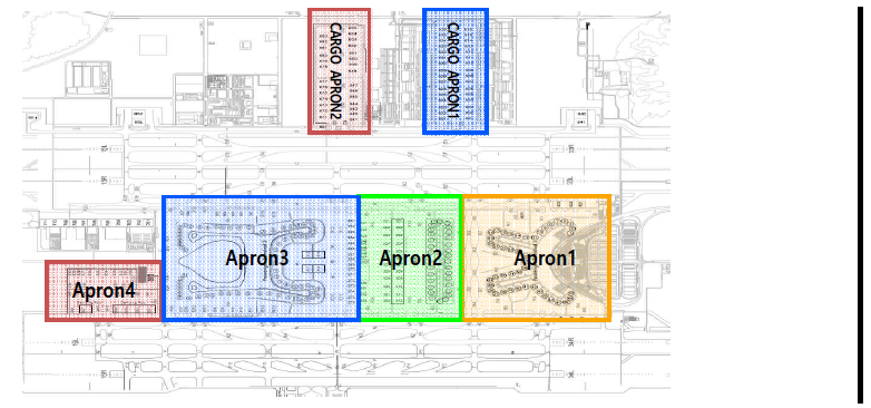
Diagram of Apron 1·2·3·4 and Cargo Apron 1·2
-
Pilots are strongly encouraged to check the availability of intersection departure before start-up. Declared distance for intersection departure are detailed in AD 2.13 DECLARED DISTANCES. For the purpose of performance calculations the standard intersection departure points are:
-
RWY 15R - B6 / K
-
RWY 33L - B1 / J
-
RWY 16L - N6 / V / U
-
RWY 34R - N1 / T
-
-
Intersection departures may be initiated by ATC to expedite traffic flow. Pilots must advise ATC if they are not able to comply with this request to prevent additional delay or sequence change.
-
ATC will consider all aircrafts at the RWY holding point as able to commence line-up and take-off roll immediately on receiving clearance from ATC, unless otherwise instructed. Pilots should note that ATC expects pre-departure cockpit checks to be completed prior to entering the runway and take-off checks that must be made on the runway are kept to the minimum required. Pilots not ready when reaching the RWY holding point shall advise ATC as early as possible before reaching to RWY holding point.
-
When line-up or take-off clearance is issued, ATC will expect and has planned on seeing movement within 10 seconds.
-
Normally ATC will apply ICAO wake vortex separation minima between successive departures. If more separation than prescribed minima is required, pilot shall notify ATC before entering the RWY.
-
Departures will normally be cleared in the order in which they are ready for take-off(First Come, First Served), however deviations may be made from this principle to facilitate the maximum number of departures with the least average delay considering following factors:
-
Types of aircraft and their relative performance;
-
Routes to be followed after take-off
-
Any specified minimum departure interval between take-off
-
Need to apply wake turbulence separation minima;
-
Aircraft which should be afforded priority; and
-
Aircraft subject to ATFM requirements
-
-
For aircraft subject to ATFM requirements, it is the responsibility of the pilot and the operator to ensure that the aircraft is ready to taxi in time to meet any required departure time, bearing in mind that once a departure sequence is established on the taxiway system, it can be difficult, and sometimes impossible, to change the order.
The runway 33L/R or 34L/R is recommended to be in use to the extent of 8 kts tailwind. If unable to comply with this procedure, notify ATC of the reason 20 minutes prior to ETD or ETA. Delay may be possible depend on traffic situation.
|
Time(UTC) |
Departure |
Arrival |
|
0000~2359 |
15R/33L, 16L/34R |
15L/33R, 16R/34L |
※ The above times and runways in use may be changed if necessary due to ATC purposes, scheduled preventive maintenance time, weather, ground conditions and traffic volume.
1.8 Flight limitations
-
The use of this airport for training purpose is prohibited. The deliberate simulation of engine failure is not permitted whilst on approach to or departure from the airport.
-
The use of this airport by light sports aircraft, ultra-light vehicles and lighter than air is prohibited.
Incheon Apron issues Push-back or Taxi instructions, approval, and/or necessary information to aircraft, vehicles and personnel within Apron areas(Apron 1, 2, 3, 4, cargo Apron 1, 2 and maintenance Apron) and deicing pads.
Pilots should always operate transponders with XPDR(and AUTO if available) except for fully parking aircraft on stand.
-
General
-
A-CDM is a process that allows air traffic controllers, airport operators, aircraft operators(AO), ground handling agents(GHA), pilots and air traffic flow managers to exchange operational information and work together to efficiently manage operations at aerodrome.
-
Definitions Commonly Used Terms in A-CDM.
-
Target Off Block Time(TOBT) - The time that an AO or GHA estimates that an aircraft will be ready, all doors closed, boarding bridge removed, push-back vehicle available and ready to start up / push-back immediately upon reception of clearance from the ATC.
-
Target Start up Approval Time(TSAT) - The time provided by ATC taking into account TOBT, Calculated Take-Off Time(CTOT) and/or the traffic situation that an aircraft can expect startup / push-back approval.
-
-
The operation of A-CDM at Incheon Airport will be phased due to ATC environmental restrictions. TSAT will not be provided to all departure flights. The flights subject to Pre-Departure Sequencing are limited to ATFM regulated flights during first operational phase.
-
TSAT will not be provided to the aircraft in de-icing operation.
-
TOBT and TSAT will be displayed on VDGS in UTC for the improvement of A-CDM operation.
-
-
A-CDM Procedures
-
Incheon Airport A-CDM Portal System will automatically calculate system TOBT for each departure flight taking into account the Estimated In-Block Time/Actual In-Block Time(EIBT/AIBT), Minimum Turnaround Time(MTTT) and Estimated Off Block Time (EOBT).
-
AO or GHA can manually update the system generated TOBT from 90 minutes prior to EOBT.
-
If the prediction of departure readiness (new TOBT) differs more than 5 minutes from the previous TOBT, AO or GHA shall update TOBT.
-
TOBT shall not deviate from EOBT by more than 15 minutes. If TOBT deviates from EOBT by more than 15 minutes, AO has to initiate an delay message. When EOBT is modified, TOBT is automatically modified to the value of EOBT.
-
TOBT shall be updated through the following channels:
-
A-CDM portal and mobile web; or
-
Flight Information Assistant (FIA) at PBB boarding rooms
-
-
TOBT information is available through the following channels:
-
A-CDM portal and mobile web; or
-
Flight Information Assistant (FIA) at PBB boarding rooms; or
-
Visual Docking Guidance System(VDGS); or
-
Radio communication with AO or GHA
-
-
TSAT will be calculated by taking into account factors such as TOBT, CTOT, Estimated Taxi-Out Time(EXOT) and ATC separation standards etc. Thus the accuracy of TOBT is vital to an optimal TSAT.
-
AO or GHA are strongly encouraged to update TOBT as soon as any expected delay to the aircraft readiness for push-back is made available to avoid unnecessary hold-ups.
-
TSAT information is available through the following channels:
-
A-CDM portal and mobile web; or
-
Flight Information Assistant (FIA) at PBB boarding rooms; or
-
Visual Docking Guidance System(VDGS); or
-
Radio communication with GHA or AO; or
-
INCHEON APRON (in case VDGS is unserviceable)
-
-
-
Non A-CDM Procedures
-
The non A-CDM procedure is applicable when TOBT and TSAT references used in A-CDM mode of operations become unavailable due to system issues or maintenance.
-
If unable to refer TOBT through any channels, pilot shall contact INCHEON DELIVERY for ATC clearance via voice RTF or Data-link Departure Clearance Service(DCL) from EOBT -10 minutes.
-
-
Pilot shall ensure aircraft is ready for push-back at TOBT.
-
Pilot shall maintain communication with the AO / GHA as they are responsible for updating the TOBT. Pilot shall notify the AO / GHA to update the TOBT if it is expected to differ by 5 minutes or more.
-
ATC clearance can be requested via voice RTF or Data-link Departure Clearance Service(DCL) from TOBT -10 minutes to +5 minutes.
-
ATC will update TSAT changes if any, before push-back. Note that TSAT displayed on VDGS may not be final and can be revised due to en-route clearance restrictions, ground congestion or flow management.
-
Pilot with TSAT shall contact INCHEON APRON to request engine start-up and push-back within 5 minutes of TSAT after obtaining ATC clearance. Pilot without TSAT shall contact INCHEON APRON after obtaining ATC clearance when ready for start-up and push-back. The pilot provide the following:
-
Call sign
-
Gate/Stand number
-
TSAT (If applicable)
-
-
INCHEON APRON may swap push-back sequencing based on TSAT and real-time readiness of aircraft to maximise apron and runway capacity and to reduce the overall delay to traffic as and when required.
-
If a flight is unable to commence push-back by TSAT + 5 minutes due to the aircraft being unready, ATC clearance and TSAT will be cancelled. Pilot must notify the AO / GHA to update the TOBT for a new TSAT before requesting for a new ATC clearance. This also applies to aircraft returning back to blocks after push-back.
-
In case of engine start-up with GPU at gates due to APU malfunction or failure, pilot needs to contact INCHEON APRON earlier than TSAT window(± 5 minutes) considering the time required for engine start-up and push-back.
-
All aircraft to be taxied within the apron shall set their engine thrusts to idle. In case of using breakaway thrust, it should be minimized, especially when commencing taxiing from stands(NR. 814, 815, 816, 817) and starting points(Point 33, 34, 35, 36) in Apron 3 for ground safety.
-
Prior to request for push-back clearance, pilot shall report “READY/REQUEST” to Incheon Apron. The term “READY/REQUEST” means :
-
Push-back tractor has been connected;
-
Boarding bridge is detached and at stand-by position; and
-
Wing walkers are ready and positioned for push-back.
Push-back clearance will be provided only after Incheon Apron has received “READY/REQUEST” by pilot.
-
-
The smaller aircraft(business jets) ingress and egress procedures at designated deicing pads shall follow the instructions of Incheon Apron. Deicing pads are self-maneuvering stands (i.e. taxi out with no push-back). In case of M North zone assigned not for deicing, aircraft shall be pushed back for departure.
-
There are several blue lines in Apron 1 and 3
Locations : Right behind Gates 9, 15, 21, 22, 32, 33, 39, 45, 49 in Apron 1, and 237, 238, 239, 240, 258, 259, 260, 261 in Apron 3.
The aircraft of those gates shall be pushed back along blue line until their nose-wheels are on the specific taxilane.
-
Prior to request for taxi clearance in apron area, pilot must report “READY/REQUEST” to Incheon Apron. The term “READY/REQUEST” means :
-
Push-back tractor has been disconnected;
-
Ground personnel, vehicles, equipment, obstacles are clear of aircraft; and
-
Aircraft is fully ready to taxi.
Taxi clearance will be provided only after Incheon Apron has received “READY/REQUEST” by pilot, and pilot shall not move without taxi clearance.
-
-
To avoid delay to other aircraft using 'Apron 1 and 3' area, aircraft should be ready to taxi as soon as the push-back manoeuvre and engine start procedure are completed. The push-back for gate 17, 18, 19, 20, 21, 33, 34, 35, 36 is onto taxilane R7, for gate 236R, 237, 238, 239, 240, 241, 257, 258, 259, 260, 261, 261R is onto taxilane R12, and for gate 208R, 290R is onto taxilane R17 therefore to avoid delays to other traffic it is essential that the aircraft should be ready to taxi as soon as the push-back manoeuvre is completed. If aircraft are unable to comply with these procedures, pilots shall immediately inform Incheon Apron in order that alternative taxi instructions may be issued to other aircraft.
-
When an aircraft have any problem which can’t make it taxi right after push back, the pilot should report to Apron control. And then the pilot will be instructed to return gate or to move other place to avoid blocking taxilanes.
-
Delays may be expected due to other aircraft to push back or to taxi as distances between aircraft gates/stands vary. If push-back is delayed due to apron traffic conditions, TSAT will remain valid even if it exceeds TSAT + 5 minutes. TOBT needs not to be updated for such situations.
-
The following tables describe the procedures for push-back of aircraft from gates with airbridges and stands. Incheon Apron will issue specific instructions to the pilot if it is necessary to expedite traffic movement.
Most gates and stands have several pushback procedures. Pushback instructions shall be issued including direction (only 4 directions are used) or specific position when necessary. Incheon Apron will issue a pushback instruction according to the use of runway or certain traffic condition.
-
When The aircraft push back onto taxilane R2 or R3 with facing south, the pilot shall be taxied with idle power for ground safety.
-
The aircraft that have been approved for push-back by Incheon Apron must set the Mode A code assigned by ATC prior to push-back.
-
The pilots and vehicle operators should look out all directions as they are instructed by the Incheon Apron and also obey emergency stop instruction given by any team member.
-
The aircraft that are moving after stopping at 4E and 5W must move with minimum power.
|
Aircraft Stands |
Pushback Procedures |
Phraseology |
|---|---|---|
|
Apron 1 | ||
|
1 and 2 |
The aircraft shall be pushed back to face north along blue line until its nosewheel is at spot 1. |
Pushback approved to point 1 |
|
3 |
The aircraft shall be pushed back onto taxilane R1 to face north. |
Pushback approved to face north |
|
The aircraft shall be pushed back to face north along blue line until its nosewheel is at spot 1. |
Pushback approved to point 1 | |
|
6 |
The aircraft shall be pushed back onto taxilane R1 to face north. |
Pushback approved to face north |
|
The aircraft shall be pushed back to face south along taxilane R1 until the specific gate position. |
Pushback approved to face south abeam gate(number) | |
|
7 |
The aircraft shall be pushed back onto taxilane R1 to face north. |
Pushback approved to face north |
|
The aircraft shall be pushed back to face south along taxilane R1 until the specific gate position. |
Pushback approved to face south abeam gate(number) | |
|
The aircraft shall be pushed back onto the stand 825 on taxilane R5 to face south. |
Pushback approved to stand 825 | |
|
8 |
The aircraft shall be pushed back onto taxilane R1 to face south. |
Pushback approved to face south |
|
The aircraft shall be pushed back to face north along taxilane R1 until the specific gate position. |
Pushback approved to face north abeam gate(number) | |
|
The aircraft shall be pushed back onto the stand 825 on taxilane R5 to face south. |
Pushback approved to stand 825 | |
|
9 |
The aircraft shall be pushed back to face south along blue line until its nosewheel is at R1. |
Pushback approved to face south |
|
The aircraft shall be pushed back onto taxilane R1 to face north. |
Pushback approved to face north | |
|
The aircraft shall be pushed back onto the stand 825 on taxilane R5 to face south. |
Pushback approved to stand 825 | |
|
10, 11 and 12 |
The aircraft shall be pushed back onto taxilane R1 to face south. |
Pushback approved to face south |
|
The aircraft shall be pushed back onto taxilane R1 to face north. |
Pushback approved to face north | |
|
14 |
The aircraft shall be pushed back onto taxilane R1 to face south. |
Pushback approved to face south |
|
The aircraft shall be pushed back onto taxilane R1 to face north until gate 10 to minimize jet blast effect. |
Pushback approved to face north | |
|
The aircraft shall be pushed back onto the spot 53R on A6 to face west. |
Pushback approved to spot 53Romeo | |
|
15 |
The aircraft shall be pushed back to face north along blue line until its nosewheel is at R1. |
Pushback approved to face north |
|
The aircraft shall be pushed back onto taxilane R1 to face south. |
Pushback approved to face south | |
|
The aircraft shall be pushed back onto the spot 53R on A6 to face west. |
Pushback approved to spot 53Romeo | |
|
16 |
The aircraft shall be pushed back onto taxilane R1 to face north. |
Pushback approved to face north |
|
The aircraft shall be pushed back onto taxilane R1 to face south. |
Pushback approved to face south | |
|
The aircraft shall be pushed back onto the spot 53R on A6 to face west. |
Pushback approved to spot 53Romeo | |
|
17 |
The aircraft shall be pushed back onto taxilane R1 to face north. |
Pushback approved to face north |
|
The aircraft shall be pushed back onto taxilane R7 to face east. |
Pushback approved to face east on R7 | |
|
The aircraft shall be pushed back onto the spot 53R on A6 to face west. |
Pushback approved to spot 53Romeo | |
|
18 |
The aircraft shall be pushed back onto taxilane R7 to face east. |
Pushback approved to face east |
|
The aircraft shall be pushed back onto taxilane R7 to face west. |
Pushback approved to face west | |
|
The aircraft shall be pushed back to face north along taxilane R1 until the specific gate position. |
Pushback approved to face north on R1 abeam gate (number) | |
|
19 |
The aircraft shall be pushed back onto taxilane R7 to face east. |
Pushback approved to face east |
|
The aircraft shall be pushed back onto taxilane R7 to face west. |
Pushback approved to face west | |
|
The aircraft shall be pushed back to face north along taxilane R1 until the specific gate position. |
Pushback approved to face north on R1 abeam gate (number) | |
|
The aircraft shall be pushed back to face north along taxilane R2 until its nosewheel is at spot 2. |
Pushback approved to point 2 | |
|
20 |
The aircraft shall be pushed back onto taxilane R7 to face east. |
Pushback approved to face east |
|
The aircraft shall be pushed back onto taxilane R7 to face west. |
Pushback approved to face west | |
|
The aircraft shall be pushed back to face north along taxilane R2 until its nosewheel is at spot 2. |
Pushback approved to point 2 | |
|
21 |
The aircraft shall be pushed back to face north along blue line until its nosewheel is at R2. |
Pushback approved to blue |
|
The aircraft shall be pushed back to face north until its body is on taxilane R2. |
Pushback approved to face north | |
|
The aircraft shall be pushed back onto taxilane R7 to face east. |
Pushback approved to face east on R7 | |
|
The aircraft shall be pushed back onto taxilane R7 to face west. |
Pushback approved to face west on R7 | |
|
22 |
The aircraft shall be pushed back to face north along blue line until its nosewheel is at R2. |
Pushback approved to blue |
|
The aircraft shall be pushed back to face north and then towed forward until its nosewheel is at spot 2. |
Pushback approved to point 2 | |
|
23, 24 and 26 |
The aircraft shall be pushed back to face north and then towed forward until its nosewheel is at spot 2. |
Pushback approved to point 2 |
|
The aircraft shall be pushed back to face south along blue line until its nosewheel is at spot 3. |
Pushback approved to point 3 | |
|
The aircraft shall be pushed back to face south along taxilane R2 until the specific gate number. |
Pushback approved to face south on R2 [abeam gate (number)] | |
|
27 |
The aircraft shall be pushed back to face north and then towed forward until its nosewheel is at spot 2. |
Pushback approved to point 2 |
|
The aircraft shall be pushed back to face south along blue line until its nosewheel is at spot 3. |
Pushback approved to point 3 | |
|
The aircraft shall be pushed back to face north and then towed forward until its nosewheel is at spot 4. |
Pushback approved to point 4 | |
|
The aircraft shall be pushed back to face south along taxilane R2 until the specific gate number. |
Pushback approved to face south on R2 [abeam gate (number)] | |
|
The aircraft shall be pushed back to face south along taxilane R3 until the specific gate number. |
Pushback approved to face south on R3 [abeam gate (number)] | |
|
28, 30 and 31 |
The aircraft shall be pushed back to face south along blue line until its nosewheel is at spot 3. |
Pushback approved to point 3 |
|
The aircraft shall be pushed back to face north and then towed forward until its nosewheel is at spot 4. |
Pushback approved to point 4 | |
|
The aircraft shall be pushed back to face south along taxilane R3 until the specific gate number. |
Pushback approved to face south on R3 [abeam gate (number)] | |
|
32 |
The aircraft shall be pushed back to face north along blue line until its nosewheel is at R3. |
Pushback approved to blue |
|
The aircraft shall be pushed back to face north and then towed forward until its nosewheel is at spot 4. |
Pushback approved to point 4 | |
|
33 |
The aircraft shall be pushed back to face north along blue line until its nosewheel is at R3. |
Pushback approved to blue |
|
The aircraft shall be pushed back to face north until its body is on taxilane R3. |
Pushback approved to face north | |
|
The aircraft shall be pushed back onto taxilane R7 to face east. |
Pushback approved to face east on R7 | |
|
The aircraft shall be pushed back onto taxilane R7 to face west. |
Pushback approved to face west on R7 | |
|
34 |
The aircraft shall be pushed back onto taxilane R7 to face east. |
Pushback approved to face east |
|
The aircraft shall be pushed back onto taxilane R7 to face west. |
Pushback approved to face west | |
|
The aircraft shall be pushed back to face north along taxilane R3 until its nosewheel is at spot 4. |
Pushback approved to point 4 | |
|
35 |
The aircraft shall be pushed back onto taxilane R7 to face east. |
Pushback approved to face east |
|
The aircraft shall be pushed back onto taxilane R7 to face west. |
Pushback approved to face west | |
|
The aircraft shall be pushed back to face north along taxilane R3 until its nosewheel is at spot 4. |
Pushback approved to point 4 | |
|
The aircraft shall be pushed back to face north along taxilane R4 until the specific gate position. |
Pushback approved to face north on R4 abeam gate (number) | |
|
36 |
The aircraft shall be pushed back onto taxilane R7 to face east. |
Pushback approved to face east |
|
The aircraft shall be pushed back onto taxilane R7 to face west. |
Pushback approved to face west | |
|
The aircraft shall be pushed back to face north along taxilane R4 until the specific gate position. |
Pushback approved to face north on R4 abeam gate (number) | |
|
37 |
The aircraft shall be pushed back onto taxilane R4 to face north. |
Pushback approved to face north |
|
The aircraft shall be pushed back onto taxilane R7 to face west. |
Pushback approved to face west on R7 | |
|
The aircraft shall be pushed back onto taxilane R6 to face north. |
Pushback approved to face north on R6 | |
|
38 |
The aircraft shall be pushed back onto taxilane R4 to face south. |
Pushback approved to face south |
|
The aircraft shall be pushed back onto taxilane R4 to face north. |
Pushback approved to face north | |
|
39 |
The aircraft shall be pushed back onto taxilane R4 to face south. |
Pushback approved to face south |
|
The aircraft shall be pushed back to face north along blue line until its nosewheel is at R4. |
Pushback approved to face north | |
|
40, 41, 42 and 43 |
The aircraft shall be pushed back onto taxilane R4 to face south. |
Pushback approved to face south |
|
The aircraft shall be pushed back onto taxilane R4 to face north. The aircraft of gate 40 shall be pushed back to face north until gate 43 to minimize jet blast effect. |
Pushback approved to face north | |
|
45 |
The aircraft shall be pushed back to face south along blue line until its nosewheel is at R4. |
Pushback approved to face south |
|
The aircraft shall be pushed back onto taxilane R4 to face north. |
Pushback approved to face north | |
|
The aircraft shall be pushed back onto taxilane R6 to face south. |
Pushback approved to face south on R6 | |
|
46 |
The aircraft shall be pushed back onto taxilane R4 to face south. |
Pushback approved to face south |
|
The aircraft shall be pushed back onto taxilane R4 to face north. |
Pushback approved to face north | |
|
The aircraft shall be pushed back onto taxilane R6 to face south. |
Pushback approved to face south on R6 | |
|
47 and 48 |
The aircraft shall be pushed back onto taxilane R4 to face north. |
Pushback approved to face north |
|
The aircraft shall be pushed back to face south along taxilane R4 until the specific gate position. |
Pushback approved to face south abeam gate (number) | |
|
The aircraft shall be pushed back to face south along taxilane R6. |
Pushback approved to face south on R6 | |
|
49 |
The aircraft shall be pushed back to face north along blue line until its nosewheel is at R4. |
Pushback approved to face north |
|
The aircraft shall be pushed back along yellow line until its nosewheel is at spot 5. |
Pushback approved to point 5 | |
|
50 |
The aircraft shall be pushed back along yellow line until its nosewheel is at spot 5. |
Pushback approved to point 5 |
|
103 |
The aircraft shall be pushed back onto taxilane AS to face east. |
Pushback approved to face east |
|
The aircraft shall be pushed back onto taxilane R1 to face south. |
Pushback approved to face south on R1 | |
|
105, 107, 109, 111, 113, 115, 117, 119, 121, 123, 125, 127 and 129 |
The aircraft shall be pushed back onto taxilane AS to face east. |
Pushback approved to face east |
|
The aircraft shall be pushed back onto taxilane AS to face west. |
Pushback approved to face west | |
|
131 |
The aircraft shall be pushed back onto taxilane R4 to face south. |
Pushback approved to face south |
|
The aircraft shall be pushed back onto taxilane AS to face west. |
Pushback approved to face west | |
|
132 |
The aircraft shall be pushed back onto taxilane R4 to face south. |
Pushback approved to face south |
|
Apron 2 | ||
|
101 |
The aircraft shall be pushed back onto taxilane R1 to face north. |
Pushback approved to face north |
|
102 |
The aircraft shall be pushed back onto taxilane R1 to face north. |
Pushback approved to face north |
|
The aircraft shall be pushed back onto taxilane R9 to face east. |
Pushback approved to face east. | |
|
104, 106, 108, 110, 112, 114, 118, 122, 124, 126, 128 |
The aircraft shall be pushed back onto taxilane R9 to face east. |
Pushback approved to face east |
|
The aircraft shall be pushed back onto taxilane R9 to face west. |
Pushback approved to face west | |
|
130 |
The aircraft shall be pushed back onto taxilane R9 to face west. |
Pushback approved to face west |
|
The aircraft shall be pushed back onto taxilane R4 to face north. |
Pushback approved to face north on R4 | |
|
301 |
The aircraft shall be pushed back onto taxilane R10 to face east. |
Pushback approved to face east |
|
302 to 311 (309A/B, 310A/B, 311A/B) |
The aircraft shall be pushed back onto taxilane R10 to face east. |
Pushback approved to face east |
|
The aircraft shall be pushed back onto taxilane R10 to face west. |
Pushback approved to face west | |
|
312 |
The aircraft shall be pushed back onto taxilane R10 to face west. |
Pushback approved to face west |
|
321 |
The aircraft shall be pushed back onto taxilane RG to face east. |
Pushback approved to face east |
|
322 to 331 (329A/B, 330A/B, 331A/B) |
The aircraft shall be pushed back onto taxilane RG to face east. |
Pushback approved to face east |
|
The aircraft shall be pushed back onto taxilane RG to face west. |
Pushback approved to face west | |
|
332 |
The aircraft shall be pushed back onto taxilane RG to face west. |
Pushback approved to face west |
|
341, 341R/L |
The aircraft shall be pushed back onto taxilane RG to face east. |
Pushback approved to face east |
|
342 to 352 (342R/L, 343R/L, 345R, 347R, 352R/L) |
The aircraft shall be pushed back onto taxilane RG to face east. |
Pushback approved to face east |
|
The aircraft shall be pushed back onto taxilane RG to face west. |
Pushback approved to face west | |
|
353, 353R/L |
The aircraft shall be pushed back onto taxilane RG to face west. |
Pushback approved to face west |
|
Apron 3 | ||
|
208 to 209 |
The aircraft shall be pushed back onto taxilane RW to face east. |
Pushback approved to face east |
|
The aircraft shall be pushed back to face east until its nosewheel is at spot 54. |
Pushback approved to point 54 | |
|
The aircraft shall be pushed back onto taxilane R24 to face south. |
Pushback approved to face south on R24 | |
|
210 to 211 |
The aircraft shall be pushed back onto taxilane RW to face east. |
Pushback approved to face east |
|
The aircraft shall be pushed back onto taxilane RW to face west. |
Pushback approved to face west | |
|
The aircraft shall be pushed back to face east and then towed forward until its nosewheel is at spot 54. |
Pushback approved to point 54 | |
|
212 to 213 |
The aircraft shall be pushed back onto taxilane RW to face east. |
Pushback approved to face east |
|
The aircraft shall be pushed back onto taxilane RW to face west. |
Pushback approved to face west | |
|
214 to 215 |
The aircraft shall be pushed back onto taxilane RW to face east. |
Pushback approved to face east |
|
The aircraft shall be pushed back onto taxilane RW to face west. |
Pushback approved to face west | |
|
The aircraft shall be pushed back to face north until its nosewheel is at spot 53. |
Pushback approved to point 53 | |
|
214R |
The aircraft shall be pushed back to face north until its nosewheel is at spot 53. |
Pushback approved to point 53 |
|
The aircraft shall be pushed back onto taxilane R4 until clear of R17 to face south. |
Pushback approved to face south | |
|
The aircraft shall be pushed back to face south and then towed forward until its nosewheel is at spot 52. |
Pushback approved to point 52 | |
|
216 |
The aircraft shall be pushed back onto taxilane R4 to face south. |
Pushback approved to face south |
|
The aircraft shall be pushed back onto taxilane R4 to face north. |
Pushback approved to face north | |
|
The aircraft shall be pushed back to face south and then towed forward until its nosewheel is at spot 52. |
Pushback approved to point 52 | |
|
The aircraft shall be pushed back to face north and then towed forward until its nosewheel is at spot 53. |
Pushback approved to point 53 | |
|
217 to 218 |
The aircraft shall be pushed back onto taxilane R4 to face south. |
Pushback approved to face south |
|
The aircraft shall be pushed back onto taxilane R4 to face north. |
Pushback approved to face north | |
|
The aircraft shall be pushed back to face south until its nosewheel is at spot 52. |
Pushback approved to point 52 | |
|
219 to 222 (224L) |
The aircraft shall be pushed back onto taxilane R4 to face south. |
Pushback approved to face south |
|
The aircraft shall be pushed back onto taxilane R4 to face north. |
Pushback approved to face north | |
|
224 (224R) |
The aircraft shall be pushed back onto taxilane R4 to face south. |
Pushback approved to face south |
|
The aircraft shall be pushed back onto taxilane R4 to face north. |
Pushback approved to face north | |
|
The aircraft shall be pushed back to face north and then towed forward until its nosewheel is at spot 51. |
Pushback approved to point 51 | |
|
225 to 236 (231R/L, 232R/L) |
The aircraft shall be pushed back onto taxilane R4 to face south. |
Pushback approved to face south |
|
The aircraft shall be pushed back onto taxilane R4 to face north. |
Pushback approved to face north | |
|
236R |
The aircraft shall be pushed back onto taxilane R4 to face south. |
Pushback approved to face south |
|
The aircraft shall be pushed back onto taxilane R12 to face west. |
Pushback approved to face west | |
|
237 |
The aircraft shall be pushed back onto taxilane R4 to face south. |
Pushback approved to face south |
|
The aircraft shall be pushed back to face north along blue line until its nosewheel is at R12. |
Pushback approved to blue | |
|
The aircraft shall be pushed back onto taxilane R12 to face west. |
Pushback approved to face west | |
|
238, 239 |
The aircraft shall be pushed back to face north along blue line until its nosewheel is at R12. |
Pushback approved to blue |
|
The aircraft shall be pushed back onto taxilane R12 to face east. |
Pushback approved to face east | |
|
The aircraft shall be pushed back onto taxilane R12 to face west. |
Pushback approved to face west | |
|
The aircraft shall be pushed back onto taxilane R4 to face south. |
Pushback approved to face south | |
|
The aircraft shall be pushed back to face south until its nosewheel is at spot 31 (or 32). |
Pushback approved to point 31(32) | |
|
239R |
The aircraft shall be pushed back onto taxilane R12 to face east. |
Pushback approved to face east |
|
The aircraft shall be pushed back onto taxilane R12 to face west. |
Pushback approved to face west | |
|
The aircraft shall be pushed back to face south until its nosewheel is at spot 31 (or 32). |
Pushback approved to point 31(32) | |
|
240 |
The aircraft shall be pushed back to face north along blue line until its nosewheel is at R12. |
Pushback approved to blue |
|
The aircraft shall be pushed back to face south until its nosewheel is at spot 31 (or 32). |
Pushback approved to point 31(32) | |
|
The aircraft shall be pushed back onto taxilane R12 to face east. |
Pushback approved to face east | |
|
241 |
The aircraft shall be pushed back to face south until its nosewheel is at spot 32. |
Pushback approved to point 32 |
|
The aircraft shall be pushed back to face south and then towed forward until its nosewheel is at spot 31. |
Pushback approved to point 31 | |
|
The aircraft shall be pushed back to face south until its body is on taxilane RC. |
Pushback approved to face south | |
|
The aircraft shall be pushed back onto the stand 816 (or 817) to face west. |
Pushback approved to stand 816(817) | |
|
The aircraft shall be pushed back onto taxilane R12 to face east. |
Pushback approved to face east on R12 | |
|
The aircraft shall be pushed back onto taxilane R12 to face west. |
Pushback approved to face west on R12 | |
|
242 |
The aircraft shall be pushed back to face south and then towed forward until its nosewheel is at spot 31 (or 32). |
Pushback approved to point 31(32) |
|
The aircraft shall be pushed back to face west until its nosewheel is at spot 33. |
Pushback approved to point 33 | |
|
The aircraft shall be pushed back onto the stand 817 (or 816) to face west. |
Pushback approved to stand 817(816) | |
|
The aircraft shall be pushed back onto taxilane RC to face north. |
Pushback approved to face north | |
|
243, 245 |
The aircraft shall be pushed back to face south and then towed forward until its nosewheel is at spot 32 (or 31). |
Pushback approved to point 32(31) |
|
The aircraft shall be pushed back to face west until its nosewheel is at spot 33 (or 34). |
Pushback approved to point 33(34) | |
|
The aircraft shall be pushed back onto taxilane RC to face north. |
Pushback approved to face north | |
|
The aircraft shall be pushed back onto the stand 817 to face west. |
Pushback approved to stand 817 | |
|
246 |
The aircraft shall be pushed back to face south and then towed forward until its nosewheel is at spot 32 (or 31). |
Pushback approved to point 32(31) |
|
The aircraft shall be pushed back to face west until its nosewheel is at spot 33 (or 34). |
Pushback approved to point 33(34) | |
|
The aircraft shall be pushed back onto taxilane RC to face north. |
Pushback approved to face north | |
|
247 |
The aircraft shall be pushed back onto taxilane RC (or RF) to face west. |
Pushback approved to face west
|
|
The aircraft shall be pushed back to face south and then towed forward until its nosewheel is at spot 32 (or 31). |
Pushback approved to red 32(31) | |
|
The aircraft shall be pushed back to face west until its nosewheel is at spot 33 (or 34). |
Pushback approved to point 33(34) | |
|
The aircraft shall be pushed back onto taxilane RC (or RB) to face north. |
Pushback approved to face north
| |
|
The aircraft shall be pushed back to face north and then towed forward until its nosewheel is at spot 39. |
Pushback approved to point 39 | |
|
248, 249 |
The aircraft shall be pushed back onto taxilane RC (or RF) to face west. |
Pushback approved to face west
|
|
The aircraft shall be pushed back to face west until its nosewheel is at spot 33 (or 34). |
Pushback approved to point 33(34) | |
|
The aircraft shall be pushed back onto taxilane RC (or RB) to face north. |
Pushback approved to face north
| |
|
The aircraft shall be pushed back to face north and then towed forward until its nosewheel is at spot 39. |
Pushback approved to point 39 | |
|
250 |
The aircraft shall be pushed back onto taxilane RC (or RF) to face east. |
Pushback approved to face east (face east on RF) |
|
The aircraft shall be pushed back onto taxilane RA (or RF) to face west. |
Pushback approved to face west (face west on RF) | |
|
The aircraft shall be pushed back to face west and then towed forward until its nosewheel is at spot 34. |
Pushback approved to point 34 | |
|
The aircraft shall be pushed back to face east and then towed forward until its nosewheel is at spot 35. |
Pushback approved to point 35 | |
|
The aircraft shall be pushed back onto taxilane RB to face north. |
Pushback approved to face north | |
|
The aircraft shall be pushed back to face north and then towed forward until its nosewheel is at spot 39. |
Pushback approved to point 39 | |
|
251, 252 |
The aircraft shall be pushed back onto taxilane RA (or RF) to face east. |
Pushback approved to face east
(face
|
|
The aircraft shall be pushed back to face east and then towed forward until its nosewheel is at spot 35 (or 36). |
Pushback approved to point 35(36) | |
|
The aircraft shall be pushed back onto taxilane RA (or RB) to face north. |
Pushback approved to face north
| |
|
The aircraft shall be pushed back to face north and then towed forward until its nosewheel is at spot 39. |
Pushback approved to point 39 | |
|
253 |
The aircraft shall be pushed back onto taxilane RA (or RF) to face east. |
Pushback approved to face east
(face
|
|
The aircraft shall be pushed back to face east until its nosewheel is at spot 35 (or 36). |
Pushback approved to point 35(36) | |
|
The aircraft shall be pushed back to face south and then towed forward until its nosewheel is at spot 37 (or 38). |
Pushback approved to point 37(38) | |
|
The aircraft shall be pushed back onto taxilane RA (or RB) to face north. |
Pushback approved to face north (face north on RB) | |
|
The aircraft shall be pushed back to face north and then towed forward until its nosewheel is at spot 39. |
Pushback approved to point 39 | |
|
254 |
The aircraft shall be pushed back to face east until its nosewheel is at spot 35 (or 36). |
Pushback approved to point 35(36) |
|
The aircraft shall be pushed back to face south and then towed forward until its nosewheel is at spot 37(or 38). |
Pushback approved to point 37(38) | |
|
The aircraft shall be pushed back onto taxilane RA to face north. |
Pushback approved to face north | |
|
255 |
The aircraft shall be pushed back to face east until its nosewheel is at spot 35 (or 36). |
Pushback approved to point 35(36) |
|
The aircraft shall be pushed back to face south and then towed forward until its nosewheel is at spot 37(or 38). |
Pushback approved to point 37(38) | |
|
The aircraft shall be pushed back onto taxilane RA to face north. |
Pushback approved to face north | |
|
The aircraft shall be pushed back onto the stand 815 to face east. |
Pushback approved to stand 815 | |
|
256 |
The aircraft shall be pushed back to face east until its nosewheel is at spot 36. |
Pushback approved to point 36 |
|
The aircraft shall be pushed back to face south and then towed forward until its nosewheel is at spot 37 (or 38). |
Pushback approved to point 37(38) | |
|
The aircraft shall be pushed back onto the stand 815 (or 814) to face east. |
Pushback approved to stand 815(814) | |
|
The aircraft shall be pushed back onto taxilane RA to face north. |
Pushback approved to face north | |
|
257 |
The aircraft shall be pushed back to face south until its nosewheel is at spot 37. |
Pushback approved to point 37 |
|
The aircraft shall be pushed back to face south and then towed forward until its nosewheel is at spot 38. |
Pushback approved to point 38 | |
|
The aircraft shall be pushed back to face south until its body is on taxilane RA. |
Pushback approved to face south | |
|
The aircraft shall be pushed back onto the stand 814 (or 815) to face east. |
Pushback approved to stand 814(815) | |
|
The aircraft shall be pushed back onto taxilane R12 to face east. |
Pushback approved to face east on R12 | |
|
The aircraft shall be pushed back onto taxilane R12 to face west. |
Pushback approved to face west on R12 | |
|
258 |
The aircraft shall be pushed back to face north along blue line until its nosewheel is at R12. |
Pushback approved to blue |
|
The aircraft shall be pushed back to face south until its nosewheel is at spot 38 (or 37). |
Pushback approved to point 38(37) | |
|
The aircraft shall be pushed back onto taxilane R12 to face west. |
Pushback approved to face west | |
|
258R |
The aircraft shall be pushed back onto taxilane R12 to face east. |
Pushback approved to face east |
|
The aircraft shall be pushed back onto taxilane R12 to face west. |
Pushback approved to face west | |
|
The aircraft shall be pushed back to face south until its nosewheel is at spot 38 (or 37). |
Pushback approved to point 38(37) | |
|
259, 260 |
The aircraft shall be pushed back to face north along blue line until its nosewheel is at R12. |
Pushback approved to blue |
|
The aircraft shall be pushed back onto taxilane R12 to face east. |
Pushback approved to face east | |
|
The aircraft shall be pushed back onto taxilane R12 to face west. |
Pushback approved to face west | |
|
The aircraft shall be pushed back to face south until its nosewheel is at spot 38 (or 37). |
Pushback approved to point 38(37) | |
|
The aircraft shall be pushed back onto taxilane R1 to face south. |
Pushback approved to face south | |
|
261 |
The aircraft shall be pushed back to face north along blue line until its nosewheel is at R12. |
Pushback approved to blue |
|
The aircraft shall be pushed back onto taxilane R12 to face east. |
Pushback approved to face east | |
|
The aircraft shall be pushed back onto taxilane R1 to face south. |
Pushback approved to face south | |
|
261R |
The aircraft shall be pushed back onto taxilane R1 to face south. |
Pushback approved to face south |
|
The aircraft shall be pushed back onto taxilane R12 to face east. |
Pushback approved to face east | |
|
262 to 268 (266R/L∼268R/L) |
The aircraft shall be pushed back onto taxilane R1 to face south. |
Pushback approved to face south |
|
The aircraft shall be pushed back onto taxilane R1 to face north. |
Pushback approved to face north | |
|
275 (275L) |
The aircraft shall be pushed back onto taxilane R1 to face south. |
Pushback approved to face south |
|
The aircraft shall be pushed back onto taxilane R1 to face north. |
Pushback approved to face north | |
|
The aircraft shall be pushed back to face north and then towed forward until its nosewheel is at spot 58. |
Pushback approved to point 58 | |
|
276 to 279 (275R) |
The aircraft shall be pushed back onto taxilane R1 to face south. |
Pushback approved to face south |
|
The aircraft shall be pushed back onto taxilane R1 to face north. |
Pushback approved to face north | |
|
280 to 281 |
The aircraft shall be pushed back onto taxilane R1 to face south. |
Pushback approved to face south |
|
The aircraft shall be pushed back onto taxilane R1 to face north. |
Pushback approved to face north | |
|
The aircraft shall be pushed back to face south until its nosewheel is at spot 57. |
Pushback approved to point 57 | |
|
282 |
The aircraft shall be pushed back onto taxilane R1 to face south. |
Pushback approved to face south |
|
The aircraft shall be pushed back to face south and then towed forward until its nosewheel is at spot 57. |
Pushback approved to point 57 | |
|
The aircraft shall be pushed back onto taxilane R1 to face north. |
Pushback approved to face north | |
|
The aircraft shall be pushed back to face north and then towed forward until its nosewheel is at spot 56. |
Pushback approved to point 56 | |
|
283 |
The aircraft shall be pushed back to face south and then towed forward until its nosewheel is at spot 57. |
Pushback approved to point 57 |
|
The aircraft shall be pushed back to face north and then towed forward until its nosewheel is at spot 56. |
Pushback approved to point 56 | |
|
The aircraft shall be pushed back onto taxilane R1 to face north. |
Pushback approved to face north | |
|
The aircraft shall be pushed back onto taxilane RE to face east. |
Pushback approved to face east | |
|
283R |
The aircraft shall be pushed back to face south and then towed forward until its nosewheel is at spot 57. |
Pushback approved to point 57 |
|
The aircraft shall be pushed back to face north until its nosewheel is at spot 56. |
Pushback approved to point 56 | |
|
The aircraft shall be pushed back onto taxilane R1 to face north. |
Pushback approved to face north | |
|
284 to 285 |
The aircraft shall be pushed back onto taxilane RE to face east. |
Pushback approved to face east |
|
The aircraft shall be pushed back onto taxilane RE to face west. |
Pushback approved to face west | |
|
The aircraft shall be pushed back to face north until its nosewheel is at spot 56. |
Pushback approved to point 56 | |
|
286 to 287 |
The aircraft shall be pushed back onto taxilane RE to face east. |
Pushback approved to face east |
|
The aircraft shall be pushed back onto taxilane RE to face west. |
Pushback approved to face west | |
|
288 to 289 |
The aircraft shall be pushed back onto taxilane RE to face east. |
Pushback approved to face east |
|
The aircraft shall be pushed back onto taxilane RE to face west. |
Pushback approved to face west | |
|
The aircraft shall be pushed back to face west and then towed forward until its nosewheel is at spot 55. |
Pushback approved to point 55 | |
|
290 to 291 |
The aircraft shall be pushed back onto taxilane RE to face west. |
Pushback approved to face west |
|
The aircraft shall be pushed back to face west until its nosewheel is at spot 55. |
Pushback approved to point 55 | |
|
The aircraft shall be pushed back onto taxilane R23 to face south. |
Pushback approved to face south on R23 | |
|
362 to 375 |
The aircraft shall be pushed back onto taxilane R11 to face east. |
Pushback approved to face east |
|
The aircraft shall be pushed back onto taxilane R11 to face west. |
Pushback approved to face west | |
|
361 |
Pilot shall request start engine then taxi on stand except following aircraft : A320 series, B737 series and A220 series. |
- |
|
The aircraft shall be pushed back onto taxilane R11 to face east. |
Pushback approved to face east | |
|
376 |
Pilot shall request start engine then taxi on stand except following aircraft : A320 series, B737 series and A220 series. |
- |
|
The aircraft shall be pushed back onto taxilane R11 to face west. |
Pushback approved to face west | |
|
501 (501L/R) |
The aircraft shall be pushed back onto taxilane R1 to face south. |
Pushback approved to face south |
|
The aircraft shall be pushed back onto taxilane R1 to face north. |
Pushback approved to face north | |
|
The aircraft shall be pushed back to face north and then towed forward until its nosewheel is at spot 58. |
Pushback approved to point 58 | |
|
502 to 505 |
The aircraft shall be pushed back onto taxilane R1 to face south. |
Pushback approved to face south |
|
The aircraft shall be pushed back onto taxilane R1 to face north. |
Pushback approved to face north | |
|
506 |
The aircraft shall be pushed back onto taxilane R1 to face south. |
Pushback approved to face south |
|
The aircraft shall be pushed back onto taxilane R1 to face north. |
Pushback approved to face north | |
|
The aircraft shall be pushed back to face north and then towed forward until its nosewheel is at spot 56. |
Pushback approved to point 56 | |
|
507 |
The aircraft shall be pushed back onto taxilane R1 to face north. |
Pushback approved to face north |
|
The aircraft shall be pushed back to face south and then towed forward until its nosewheel is at spot 57. |
Pushback approved to point 57 | |
|
The aircraft shall be pushed back onto taxilane RE to face east. |
Pushback approved to face east | |
|
511 (511L/R) |
The aircraft shall be pushed back onto taxilane R4 to face south. |
Pushback approved to face south |
|
The aircraft shall be pushed back onto taxilane R4 to face north. |
Pushback approved to face north | |
|
The aircraft shall be pushed back to face north and then towed forward until its nosewheel is at spot 51. |
Pushback approved to point 51 | |
|
512 to 515 |
The aircraft shall be pushed back onto taxilane R4 to face south. |
Pushback approved to face south |
|
The aircraft shall be pushed back onto taxilane R4 to face north. |
Pushback approved to face north | |
|
516 |
The aircraft shall be pushed back onto taxilane R4 to face south. |
Pushback approved to face south |
|
The aircraft shall be pushed back onto taxilane R4 to face north. |
Pushback approved to face north | |
|
The aircraft shall be pushed back to face north and then towed forward until its nosewheel is at spot 53. |
Pushback approved to point 53 | |
|
517 |
The aircraft shall be pushed back onto taxilane R4 to face north. |
Pushback approved to face north |
|
The aircraft shall be pushed back to face south and then towed forward until its nosewheel is at spot 52. |
Pushback approved to point 52 | |
|
The aircraft shall be pushed back onto taxilane RW to face west. |
Pushback approved to face west | |
|
Apron 4 | ||
|
520 |
The aircraft shall be pushed back to face north and then towed forward until its nosewheel is at spot 41. |
Pushback approved to red 41 |
|
521 to 524 |
The aircraft shall be pushed back to face north and then towed forward until its nosewheel is at spot 41. |
Pushback approved to point 41 |
|
The aircraft shall be pushed back onto taxilane R26 to face south. |
Pushback approved to face south | |
|
522R |
The aircraft shall be pushed back onto taxilane R26 to face south. |
Pushback approved to face south |
|
525 |
The aircraft shall be pushed back to face south and then towed forward until its nosewheel is at spot 42. |
Pushback approved to point 42 |
|
The aircraft shall be pushed back onto taxilane R26 to face north. |
Pushback approved to face north | |
|
526 to 528 |
The aircraft shall be pushed back to face south then towed forward until its nosewheel is at spot 42. |
Pushback approved to point 42 |
|
The aircraft shall be pushed back onto taxilane R26 to face north. |
Pushback approved to face north | |
|
528R, 529 to 530 |
The aircraft shall be pushed back onto taxilane R26 to face north. |
Pushback approved to face north |
|
531 to 532 |
The aircraft shall be pushed back onto taxilane R26 to face south. |
Pushback approved to face south |
|
533 |
The aircraft shall be pushed back to face north and then towed forward until its nosewheel is at spot 41. |
Pushback approved to point 41 |
|
The aircraft shall be pushed back onto taxilane R26 to face south. |
Pushback approved to face south | |
|
534 |
The aircraft shall be pushed back to face south and then towed forward until its nosewheel is at spot 42. |
Pushback approved to point 42 |
|
The aircraft shall be pushed back onto taxilane R26 to face north. |
Pushback approved to face north | |
|
535 to 536 |
The aircraft shall be pushed back onto taxilane R26 to face south. |
Pushback approved to face south |
|
541 to 544 |
The aircraft shall be pushed back onto taxilane R4 to face south. |
Pushback approved to face south |
|
The aircraft shall be pushed back onto taxilane R4 to face north. |
Pushback approved to face north | |
|
545, 547 |
The aircraft shall be pushed back to face south and then towed forward until its nosewheel is at spot 43. |
Pushback approved to point 43 |
|
The aircraft shall be pushed back onto taxilane R4 to face north. |
Pushback approved to face north | |
|
546 |
The aircraft shall be pushed back onto taxilane R4 to face north. |
Pushback approved to face north |
|
551 to 554 |
The aircraft shall be pushed back onto taxilane R4 to face south |
Pushback approved to face south |
|
The aircraft shall be pushed back onto taxilane R4 to face north. |
Pushback approved to face north | |
|
Pilot shall taxi on stand when assigned for deicing. |
- | |
|
557 |
The aircraft shall be pushed back to face south and then towed forward until its nosewheel is at spot 43. |
Pushback approved to point 43 |
|
Pilot shall taxi on stand when assigned for deicing. |
- | |
|
The aircraft shall be pushed back onto taxilane R4 to face north. |
Pushback approved to face north | |
|
558 |
The aircraft shall be pushed back onto taxilane R4 to face north. |
Pushback approved to face north |
|
Cargo Apron 1 | ||
|
601 to 614 , 621 to 634 |
The aircraft shall be pushed back onto taxilane D2 or D3 to face west. |
Pushback approved |
|
615 to 616 |
The aircraft shall be pushed back to face west and then towed forward until its nosewheel is at spot 12. |
Pushback approved to point 12 |
|
635 to 636 |
The aircraft shall be pushed back to face west and then towed forward until its nosewheel is at spot 11. |
Pushback approved to point 11 |
|
Cargo Apron 2 | ||
|
641 to 652 (652R/L) |
The aircraft shall be pushed back onto taxilane D4 to face west. |
Pushback approved |
|
653 to 655 |
The aircraft shall be pushed back to face west and then towed forward until its nosewheel is at spot 10. |
Pushback approved to point 10 |
|
671 to 681 |
The aircraft shall be pushed back onto taxilane D5 to face west. |
Pushback approved |
|
682, 683 |
The aircraft shall be pushed back to face west and then towed forward until its nosewheel is at spot 9. |
Pushback approved to point 9 |
|
Route |
Taxi Route Details |
|
Route for RWY 15R Departure |
CGO APRON → Turn Right on D → Turn Left onto K → Hold at Holding Point RWY 15L on TWY K → Turn Right on C → Turn Left on L → Hold at Holding Point RWY 15R |
|
Route for RWY 33L Departure |
CGO APRON → Turn Left on D → Turn Right onto J → Hold at Holding Point RWY 33R on TWY J → Turn Left on C → Turn Right on G → Hold at Holding Point RWY 33L |
|
Route |
Taxi Route Details |
|
Route for RWY 16L Departure |
CGO APRON → Turn Right on D → Turn Left onto K → Hold at Holding Point RWY 15L on TWY K → Turn Right onto A16 → Turn Right on A → Turn Left onto R17 → R17 →Turn Right on M → M19 → Hold at Holding Point RWY 16L |
|
Route for RWY 34R Departure |
CGO APRON → Turn Left on D → Turn Right onto J → Hold at Holding Point RWY 33R on TWY J → Turn Right onto A8 → R8 → Turn Left on M → M5 → Hold at Holding Point RWY 34R |
- Unless otherwise instructed, aircraft should use the following routes:
- Aircraft shall not proceed beyond the TCP without clearance from Incheon Ground or Tower.
|
Apron |
Apron FREQ |
Route |
TCP |
Gate/Stand |
|---|---|---|---|---|
|
Apron 1 |
121.65 Mhz |
R1 - A4 R1 - R7 R1 - R8 |
4E 7E 8W |
1 to 17 |
|
R7 R8 |
7E 8W |
18 to 36 | ||
|
R4 - M5 R4(R6) - R7 R4(R6) - R8 |
5W 7E 8W |
37 to 50 | ||
|
R7 R8 |
7E 8W |
103,105,107,109,111,113, 115,117,119,121,123,125, 127,129,131,132 | ||
|
Apron 2 |
121.8 Mhz |
R9 R10 |
9E 10W |
101,102,104,106,108,110, 112,114,118,122,124,126, 128,130 |
|
301 to 312 | ||||
|
RG |
30E 30w |
321 to 332 341 to 353 | ||
|
Apron 3 |
122.175 MHz |
R4 - R11 R4 - R12 R4 - M13 |
11E 12W 13W |
225 to 236 |
|
R1 - R11 R1 - R12 R1 - A13 |
11E 12W 13E |
262 to 268 | ||
|
R11 R12 |
11E 12W |
236R, 237 to 261, 261R 361 to 376 | ||
|
129.725 MHz |
R17 - RE R17 |
50E 17W |
208, 209 to 214, 215 516, 517 | |
|
R4 - R11 R4 - M15 |
11E 15W |
214R, 216 to 224 511 to 515 | ||
|
R1 - A15 R1 - R17 |
15E 17W |
275 to 282, 283R 501 to 505 | ||
|
RE R17 |
50E 17W |
283, 284 to 290, 291 506, 507 | ||
|
Apron 4 |
123.675 Mhz |
R4 - R11 M19 |
11E 19W |
520 to 530 531 to 536 541 to 547 551 to 554 557 to 558 |
|
Cargo Apron 1 |
123.325 MHz |
D2 D3 |
2Y 3Y |
601 to 616 621 to 636 |
|
Cargo Apron 2 |
D4 D5 |
4Y 5Y |
641 to 655 671 to 683 | |
|
Remarks Departure routes in Apron areas will be issued in detail according to runway in use and traffic movement condition by Incheon Apron. Refer to RKSI AD 2-6, 2-8 (Aerodrome Ground Movement Charts). | ||||
-
received positive ATC clearance to enter/cross the runway or taxiway, and
-
observed that the red Stop bar lights are turned off.
|
DE/ANTI-ICING PHASE |
Application of phase |
|---|---|
|
Phase 1 (BLUE) |
Initiated when snow begins and de-icing request are received. |
|
Phase 2 (YELLOW) |
Initiated when number of aircraft in the de-icing queue reaches 45 aircraft. |
|
Phase 3 (ORANGE) |
Initiated when number of aircraft in the de-icing queue reaches 80 aircraft. |
|
Phase 4 (RED) |
Initiated when number of aircraft in the de-icing queue reaches 120 aircraft. |
De-icing pads assignment will be made as pad-group.
-
A South zone : 821, 822, 823, 825 pads
-
M South zone : 831, 832, 833, 834 pads
-
M North zone : 551, 552, 553, 554, 557 pads
-
T Center zone : 814, 815, 816, 817 pads
-
Central De-icing zone : 301, 302, 303, 304, 305, 306, 307, 308, 309, 310, 311, 312 pads
-
D South zone : 841, 842 pads
-
D North zone : 851, 852 pads
-
De-icing requests and cancellations are possible through A-CDM portal system by AO or via radio communication with Incheon De-icing by flight crew.
-
Engine on de-icing is available on all de-icing pads and ACFT types applicable for engine on de-icing depend on AO or GHA.
-
Technical de-icing (landing gear, brakes, inside LE- or TE-flaps, under wing, engine inlets, fan blades and sensors/ static ports/ pitot probes) should be performed by Engine off.
-
For safety and GHA’s operational reasons(weather conditions, etc.), engine off de-icing can be applied.
-
On the de-icing pads ACFT shall hold abeam the stop line which indicates the cockpit stop position or follow the advice of the marshaller.
-
Aircrew shall control the throttle carefully, avoiding the exhausted gas causing damage to support personnel and equipment, when aircraft exit the de-icing stands.
-
During the engine on de-icing, aircrew shall keep the engine idle and set the brake. ACFT hold position until Pad control give the taxi instruction.
-
The detailed de-icing procedures are given on the ‘ICN DE-ICING ANTI-ICING PILOT BRIEF SHEET’. A copy of the sheet can be downloaded from www.airport.kr/co_en/4415/subview.do.
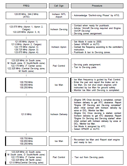
NOTE 1 : The de-icing pad will be appropriately assigned by Incheon Apron or Pad Control when aircraft approaches to de-icing zone.
NOTE 2 : Flight crews shall monitor and maintain radio contact, otherwise re-sequenced as a result of no response to 3 successive calls.
NOTE 3 : This procedures can be changed by Incheon Apron according to the volume of de-icing traffic.
NOTE 4 : Flight crews need extra caution when entering and leaving the de-icing pad, since there are GSE roads in front of or behind the de-icing pad.
-
Unless otherwise instructed, aircraft should use the following routes;
Apron
Apron FREQ
Route
TCP
Gate/Stand
Apron 1
121.65 MHz
A5 - R1
5E
1 to 12
A6 - R1
6E
14 to 17
R7 - R1
7W
1 to 17
R7
R8
7W
8E
18 to 36
R7 - R4(R6)
7W
37 to 42
M6 - R4
6W
43 to 50
R8 - R4(R6)
8E
37 to 50
R7
R8
7W
8E
103,105,107,109,111,113,115,117, 119,121,123,125,127,129,131,132
Apron 2
121.8 MHz
R9
R10
9W
10E
101,102,104,106,108,110,
112,114,118,122,124,126,
128,130
301 to 312
RG
30W
30E
321 to 332
341 to 353
Apron 3
122.175 MHz
M14 - R4
R12 - R4
14W
12E
225 to 236
R11 - R1
A14 - R1
11W
14E
262 to 268
R11
R12
11W
12E
236R, 237 to 261, 261R
361 to 376
129.725 MHz
RW
R17
50W
17E
208, 209 to 214, 215
516 to 517
M16 - R4
R17 - R4
16W
17E
214R, 216 to 224
511 to 515
M11 - R1
A16 - R1
11W
16E
275 to 282, 283R
501 to 505
RW
R17
50W
17E
283, 284 to 290, 291
506 to 507
Apron 4
122.175 MHz
R17 - R4
M18
17E
18W
520 to 530
531 to 536
541 to 547
551 to 554
557 to 558
Cargo Apron 1
123.325 MHz
D2
D3
2Y
3Y
601 to 616
621 to 636
Cargo Apron 2
D4
D5
4Y
5Y
641 to 655
671 to 683
Remarks
Arrival routes in Apron areas will be issued in detail according to runway in use and traffic movement condition by Incheon Apron. Refer to RKSI AD CHART 2-7, 2-9 (Aerodrome Ground Movement Charts)
-
Aircraft will normally be transferred to Incheon Apron prior to the TCP. Unless otherwise directed, aircraft may automatically contact Incheon Apron at the TCP.
-
Aircraft shall not proceed beyond the TCP without clearance from Incheon Apron.
-
Follow-me service is available to arriving aircraft. Pilots should make the request to Incheon Ground or Incheon Apron.
-
Aircraft shall monitor the appropriate Incheon Ground and/or Incheon Apron frequencies while taxiing.
Pilot or authorized engineer requiring engine ground runs shall contact Incheon Apron on the appropriate frequency (refer to 2.20.3.4.1) and provide the following :
-
Call sign or registration number
-
Gate/Stand number
-
Type of ground engine run, engine start or performance check Incheon Apron should be advised on its completion
Engine starts are permitted in the Apron areas. However the power setting(s) shall not exceed idle thrust.
-
Run-up area: North of maintenance Apron (Refer to RKSI AD CHART 2-3,2-4)
-
Operation Hours: 24 Hours
-
Accommodation: 2 aircraft simultaneously(only towed)
-
In case of the Run-up area U/S, temporary run-up areas can be allocated as FLW;
Temporary Run-up Areas
Remarks
14A (North part of TWY A)
122.175 MHz shall be monitored during engine performance check in temporary run-up areas.
-
All aeroplane will taxi at speeds of more than 10 kt on Taxiways A, B, C, D, M, N or P to ensure smooth traffic flow unless there is exceptional direction concerning safety factors by ATC. And if it is impracticable, pilots shall notify to ATC.
-
There are obstacles, guardrails of underpass way, near by TWY A (between A8 & A9, A12 & A13) and TWY D (between D2 & D3, D5 & D6). The heights of obstacles are less than 1 m.
Pilots should therefore closely monitor their ILS approach profile and rate of descent.
Incheon International Airport RWY 15L, RWY 15R, RWY 16L, RWY 16R, RWY 33L, RWY 33R, RWY 34L and RWY 34R have ILS CAT III equipments. Low Visibility Procedures are established for operation in a visibility of less than RVR 550 m or a cloud ceiling of less than 60 m (200 ft) or less.
-
Low visibility operations will be initiated by broadcasting "ATC LOW VISIBILITY PROCEDURES ARE IN OPERATION" via ATIS and/or appropriate radio frequencies.
-
Low visibility operations will be terminated by deleting the above mentioned message from ATIS and/or broadcasting "ATC LOW VISIBILITY OPERATIONS ARE TERMINATED" via appropriate frequencies.
1. Approval for CAT II/III Operations
-
Aircraft operators and pilots who wish to conduct ILS CAT II/III operations at Incheon International Airport shall conform with certain requirements. Details of these requirements are published in Aviation Safety Act, Article 67 and its Enforcement Regulations Article 189, which are available from :
Flight Operations Division
Seoul Regional Aviation Administration
47, Gonghang-ro 424 beon-gil, Jung-gu, Incheon,
400-718, Republic of Korea
Tel : +82-32-740-2154, 5
Fax : +82-32-740-2159
-
Foreign operators may obtain the approval from Administrator of Seoul Regional Aviation Administration by providing the following information to Administrator of Seoul Regional Aviation Administration.
1) Aircraft type and register number ;
2) The CAT II/III minima to which they intend to operate ; and
3) A copy of the category II/III certification issued by their own category authority.
-
Meteorological reports preclude ILS CAT I operations;
-
Low Visibility Procedures are in operation;
-
There is any unserviceable in a promulgated facility so that they may amend their minima.
General Special procedures and ground safeguards
Special procedures and ground safeguards will be applied during CAT II/III operations to protect aircraft from operating in low visibility and to avoid interference with the ILS signals in accordance with the provisions of ICAO Doc. 9365 - Manual of All Weather Operations, and the provisions of the Enforcement Regulations of Aviation Act, Article 210-8.
-
During low visibility operations, taxiway centerline lights will be used in conjunction with the stop bar lights as follows :
-
If the stop bar lights are turned on, the centerline lights beyond the stop bar will be turned off.
-
If the stop bar lights are turned off, the centerline lights beyond the stop bar will be turned on.
-
-
Restrictions of application on CAT-II/III holding positions : TWY G or TWY L
-
When RWY 15L for landing and RWY 15R for departure are in use at the same time, CAT-II/III holding positions on TWY G and L are not applied.
-
When RWY 33L for departure and RWY 33R for landing are in use at the same time, CAT-II/III holding positions on TWY L and G are not applied.
-
-
Arriving aircraft
-
Aircraft shall vacate the runway via the designated exit taxiways as follows; Other exit taxiways will not be lit.
RWY 15L - C2, C1, D1 or G
RWY 15R - B3, B2 or G
RWY 33L - B4, B5 or L
RWY 33R - C4, C5, D6 or L
RWY 16L - N3, N2 or S
RWY 16R - P6, P5, P4, P2 or S
RWY 34R - N4, N5 or N7
RWY 34L - P7, P8, P10, P11 or P13
Refer to Low Visibility Procedure diagram Pages.
-
All runway exits have taxiway center-line lead off lights that are color coded (green/yellow) to indicate that portion of the taxiway that is within the ILS sensitive area.
-
Pilots are required to make a 'runway vacated' call giving due allowance for the size of the aircraft to ensure that the entire aircraft have vacated the ILS critical sensitive areas.
-
-
Departing aircraft
Departing aircraft shall normally enter the runway via the designated taxiways as follows :
RWY 15L : A → L or D → L
RWY 15R : A → L, D → L, D → K → C → L
RWY 33L : A → G, D → G, D → J → C → G
RWY 33R : A → G, D → G
RWY 16L : M → N7
RWY 16R : M → V → P → P13, M → N7 → P → P13
RWY 34R : M → S
RWY 34L : M → S, M → T → P → S
Refer to Low Visibility Procedure diagram Pages.
Pilots may carry out a practice ILS CAT II/III approach at any time with a prior approval of ATC, but the full safeguarding ground procedures will not be applied and pilots should anticipate the possibility of ILS signal interference.
-
All GSE (Ground Service Equipment) vehicle roadways crossing taxiways or taxi lanes are marked in the form of zipper.
-
Pilots shall pay extra caution to the vehicles and other aircraft while taxiing in apron areas, especially ensuring enough wing-tip clearance.
All runways are available for the ICAO Code F aircraft.
The markings for RWY 15R/33L, RWY 15L/33R, RWY 16R/34L, RWY 16L/34R are located at 107.5 m from runway centerline.
-
ICAO Code F aircraft should taxi along the taxiing routes published on movement charts(refer to AIP RKSI Aerodrome ground movement chart) unless there are special instructions by ATC.
-
ICAO Code F aircraft should taxi at speed of less than 30 kt on TWY A, B, M and N because there are open channels between TWY A and B (depth 3 m), TWY N and M (depth 3.5 m). (refer to AIP RKSI Aerodrome ground movement chart)
-
ICAO Code F aircraft should taxi along the taxiing routes published on SMGCS taxi route (refer to AIP RKSI Low visibility procedure diagram) under Low Visibility Procedure(LVP) unless there are special instructions by ATC.
-
B747-8 aircraft are available on all taxiing routes.
-
A380 aircraft should taxi along the taxiing routes published on movement charts(refer to AIP RKSI Aerodrome ground movement chart) unless there are special instructions by Incheon Apron(Apron Controller). Some Apron taxiing routes are restricted as below.
A380 Unavailable Taxiing Routes
Apron 1
AS, R5
Apron 3
RF
Parts of RA, RB, RC(Except the routes between R11 and R12)
Apron 4
R26
M18, M19(R4 ~ R26 routes)
Cargo Apron 1
D2, D3
For more information on ICAO Code F aircraft operation in Maintenance Apron, Deicing Apron, Isolated Security Parking Position, and Multiple use stands, refer to RKSI AD CHART 2-4 and 2-5.
|
Stand NR. Stand NR. |
Code F ACFT | ||
|---|---|---|---|
|
A380 |
B747-8 | ||
|
Passenger Terminal 1 |
8 |
- |
O |
|
10 |
O |
O | |
|
12 |
- |
O | |
|
15 |
- |
O | |
|
17 |
O |
O | |
|
43 |
O |
O | |
|
46 |
O |
O | |
|
Passenger Terminal 2 |
224 |
O |
O |
|
225 |
O |
O | |
|
231 |
O |
O | |
|
232 |
O |
O | |
|
233 |
- |
O | |
|
234 |
- |
O | |
|
264 |
- |
O | |
|
265 |
- |
O | |
|
266 |
O |
O | |
|
267 |
O |
O | |
|
268 |
O |
O | |
|
275 |
O |
O | |
|
Concourse |
106 |
O |
O |
|
110 |
O |
O | |
|
112 |
O |
O | |
|
122 |
O |
O | |
|
126 |
O |
O | |
|
Cargo Apron 1 |
603 |
- |
O |
|
604 |
- |
O | |
|
606 |
- |
O | |
|
607 |
- |
O | |
|
616 |
- |
O | |
|
623 |
- |
O | |
|
624 |
- |
O | |
|
626 |
- |
O | |
|
627 |
- |
O | |
|
629 |
- |
O | |
|
630 |
- |
O | |
|
636 |
- |
O | |
|
Cargo Apron 2 |
641 |
O |
O |
|
644 |
O |
O | |
|
647 |
- |
O | |
|
648 |
O |
O | |
|
652 |
O |
O | |
|
655 |
- |
O | |
|
671 |
O |
O | |
|
674 |
O |
O | |
|
681 |
O |
O | |
|
Remote Stands |
322 |
O |
O |
|
323 |
O |
O | |
|
324 |
O |
O | |
|
329 |
O |
O | |
|
330 |
O |
O | |
|
331 |
O |
O | |
|
341 |
O |
O | |
|
342 |
O |
O | |
|
352 |
O |
O | |
|
353 |
O |
O | |
|
501 |
O |
O | |
|
502 |
- |
O | |
|
511 |
O |
O | |
|
512 |
- |
O | |
|
541 |
O |
O | |
|
542 |
O |
O | |
|
543 |
O |
O | |
|
544 |
O |
O | |
|
Deicing Apron |
302 |
O |
O |
|
303 |
O |
O | |
|
304 |
O |
O | |
|
309 |
O |
O | |
|
310 |
O |
O | |
|
311 |
O |
O | |
|
551 |
O |
O | |
|
552 |
O |
O | |
|
557 |
O |
O | |
|
823 |
O |
O | |
|
825 |
- |
O | |
|
831 |
O |
O | |
|
841 |
- |
O | |
|
842 |
O |
O | |
|
851 |
- |
O | |
|
852 |
O |
O | |
|
Maintenance Apron |
701 |
O |
O |
|
704 |
O |
O | |
|
705 |
O |
O | |
|
709 |
O |
O | |
|
710 |
O |
O | |
Aircraft taxiing from apron 1 to apron 2(or from apron 2 to apron 1), or from apron 2 to apron 3(or from apron 3 to apron 2) will change the frequency when approaching the transfer of control point below.
|
Apron |
Position |
TCP (Transfer of Control Point) |
|
Apron 1 ↔ Apron 2 |
Gate 103 |
1T |
|
Gate 130 |
2T | |
|
Apron 2 ↔ Apron 3 |
between ACFT stands NR. 341 & 361 |
3T |
|
between ACFT stands NR. 353 & 376 |
4T |
Refer to RKSI AD CHART 2-1, 2-3, 2-6, 2-7, 2-8, 2-9 for the position in detail.
Reduced Runway Separation Minima(RRSM) will be applied between a departing aircraft and a succeeding landing aircraft or between two successive landing aircraft.
-
RRSM will be applied when the following conditions exist :
-
Visibility of at least 5 km and ceiling not lower than 1 000 ft;
-
During the hours of daylight from 30 minutes after local sunrise to 30 minutes before local sunset;
-
No unfavorable surface wind conditions (including turbulence, wind shear, or significant tailwind(greater than 5 knots), etc);
-
The braking action shall not be adversely affected by runway contaminants;
-
The second aircraft will be able to see the first aircraft clearly and continuously until it is clear of runway
-
-
Landing clearance may be issued to an arriving aircraft while the runway is still occupied provided that there is reasonable assurance that the following separation distance will exist when the arriving aircraft crosses the runway threshold. :
-
Landing following Landing
Preceding aircraft has landed and has passed at least 2 400 m from the threshold of the landing runway, is in motion and will vacate the runway without backtracking;
-
Landing following Departure
Preceding aircraft is/will be airborne and has passed at least 2 400 m from the threshold of the landing runway.
-
-
ATC will provide traffic information when issuing the landing clearance. The following ICAO standard phraseology examples will be used :
-
“(Call sign), PRECEDING B747 VACATING RUNWAY/ABOUT TO VACATE/LANDING ROLL, CLEARED TO LAND.”
-
“(Call sign), DEPARTING A321 AHEAD ABOUT TO ROTATE, CLEARED TO LAND.”
-
- All aircraft shall taxi at speed of less than 15 kt on Taxilane bridge R17 (Taxilane R17 over bridge) to ensure safe movement.
- ICAO Code C and D aircraft could be restricted for taxiing on the bridge R17 during 60 ~ 70 kt of wind speed.
- All aircraft could be restricted for taxiing on the bridge R17 during not less than 70 kt of wind speed.
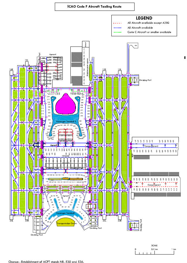
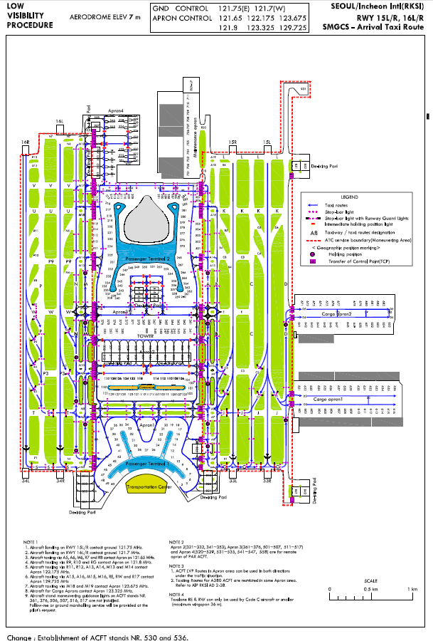
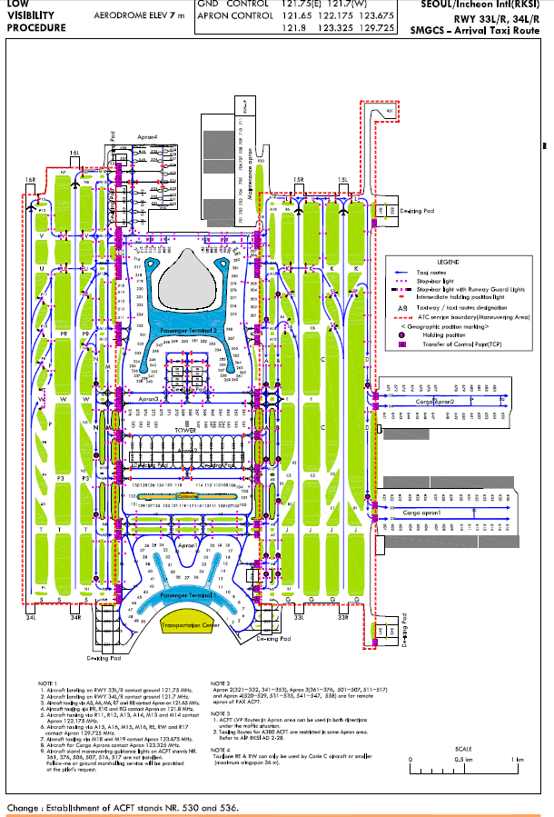
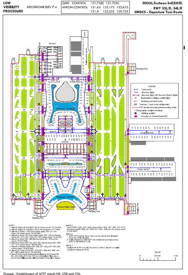
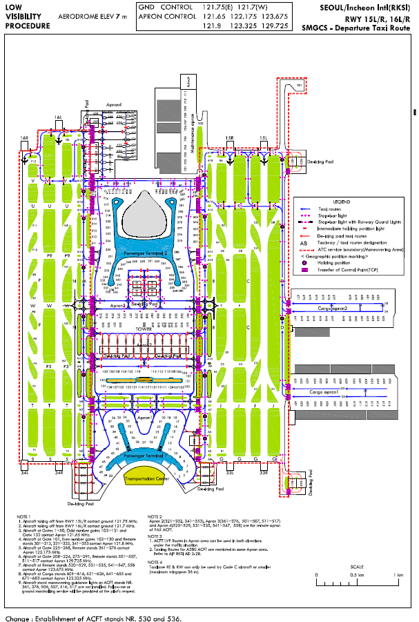
RKSI AD 2.21 NOISE ABATEMENT PROCEDURES
All departing aircraft should apply ICAO PANS-OPS (Doc 8168) Volume III Noise Abatement Take-off Climb Procedures as follows :
-
2. Runway 15L/R, 16L/R :
Noise Abatement Departure Procedure ONE or TWO (NADP ONE or NADP TWO)
a. NADP ONE : Thrust reduc tion at 1 5 00 ft above aerodrome elevation recommended
b. NADP TWO : Acceleration at 1 000 ft above aerodrome elevation recommended
c. For noise abatement and CO₂ reduction using a NADP TWO is recommended. if for safety reasons(prevention of bird strike), compliance with the recommended procedure is not possible, NADP ONE may be used.
1. Runway 33L/R, 34R/L :
- Noise Abatement Departure Procedure ONE (NADP ONE)
a. Thrust reduction at 1 500 ft above aerodrome elevation recommended.
At Passenger docking stands, primarily the stationary airport pneumatic and electrical service units shall be used.
Alternatively the airport owned mobile units shall be used.
At other stands, the airport owned mobile units shall be used.
Airborne APUs shall only be started;
- to start engine, the earliest 30 minutes before off-block time; however wide fuselage aircraft are permitted to use APU 60 minutes prior to scheduled departure time.
- if maintenance work on the aircraft makes it unavoidable; in that case the service period shall be kept as short as possible;
- if the Airport owned units are not available or unserviceable for specific aircraft types; in that case the airborne APUs shall be started at the earliest 60 minutes before off-block time and be kept in operation not more than 30 minutes after the on-block time.
In particular cases the Airport Corporation may permit longer service periods for APUs after the on-block time.
- Airport Corporation Telephone : 032-741-2458∼9.
- INCHEON APRON CONTROL : 121.65 MHz, 122.175 MHz, 121.8 MHz, 123.325 MHz, 123.675 MHz, 129.725 MHz
RKSI AD 2.22 FLIGHT PROCEDURES
The following procedures are established for all turbo jet departures from Incheon International Airport :
-
IFR ATC clearance may be obtained by Voice RTF or datalink Departure clearance Service(DCL)(via ARINC (623)).
-
Pilot shall contact INCHEON DELIVERY via voice RTF or Data-link Departure Clearance Service(DCL) from TOBT -10 minutes(in case of NON A-CDM, EOBT -10 minutes) to +5 minutes and report the following information. If initial call takes to place too early, Clearance Delivery will ask the pilot to call again at TOBT - 10 minutes. In case of DCL, reject message will be received. (refer RKSI AD 2.20 3.1 A-CDM)
-
Aircraft identification
-
Destination
-
Gate or stand number
-
ATIS code
-
-
In cases where ATC clearance is received via DCL, Pilot should follow restrictions in the remarks of ATC Clearance and acknowledge them within 5 minutes.
-
If unable to commence push-back by TSAT +5 minutes(flight with TSAT) or within 10 minutes after receiving ATC clearance(flight without TSAT) due to the aircraft being unready, ATC clearance will be cancelled. Pilot shall contact again INCHEON DELIVERY for clearances. (refer RKSI AD 2.20 3.2)
-
All aircraft shall not exceed 250 kt IAS below 10 000 ft in SEOUL TMA, unless otherwise authorized by ATC. If unable to comply with this speed restriction, state minimum speed acceptable to ATC.
-
ATC will use “NO ATC SPEED RESTRICTIONS” RTF phraseology to remove MAX 250 kt IAS below 10 000 ft.
-
speed control under radar vector :
-
When arriving traffic is being sequenced under radar direction, ATC typically will apply the following speed control :
-
Initial approach phase : 210 kt IAS
-
Base leg/HDG to final approach : 180 kt IAS
-
When established on final approach : 180 kt to 160 kt IAS
-
Thereafter to 5 DME : 160 kt IAS
-
-
These speed restrictions are essential for smooth and safe operations at high traffic loads. If an aircraft does not comply with these speed instructions, the aircraft may have to be excluded from the planned approach sequence.
-
When ATC use “RESUME NORMAL SPEED“ RTF phraseology, it means that the previously issued speed restriction by ATC is cancelled and a pilot can resume an aircraft’s preferred speed. Pilot shall note that it does not mean the removal of MAX 250 kt IAS within SEOUL TMA.
-
Fuel Dumping Area is established within SEOUL TMA as follows :
-
AREA
BELTU(37°12'18"N 125°47'59"E) : Inbound HDG 097, Left turns, 1 MIN leg
(ATC instruction : Hold west of BELTU, on HDG 097, 1 MIN leg, left turns)
PY036(37°12'28"N 126°02'24"E) : Inbound HDG 097, Left turns, 1 MIN leg
(ATC instruction : Hold west of PY036, on HDG 097, 1 MIN leg, left turns)
PY044(37°15'06"N 125°52'55"E, NCN R 250/D31) : Inbound HDG 070, Left turns, 1 MIN leg
(ATC instruction : Hold southwest of PY044, on HDG 070, 1 MIN leg, left turns)
-
ALTITUDE : At or above 6 000 ft
-
SPEED : 230 kt IAS or less
-
Area/Altitude may be changed by pilot request, traffic condition or any other safety reason.
-
Visual approach may be initiated by ATC or approved upon pilot request on traffic permitting basis when weather as follows;
-
Ceiling : At or above 2 500 ft
-
Visibility : Not less than 5 km
-
-
Independent Visual Approach(IVA) will be used at Incheon International Airport(IIA). This procedure requires accurate and consistent application of the pilot procedures and responsibilities.
-
Application
-
IVA will be used during parallel runway operations when the visibility is not less than 5 km and the ceiling is at or above 2 500 ft.
-
IVA will be initiated by ATC when the pilot reports visual runway and/or preceding aircraft while turning to the final or flying on the localizer course.
-
Pilots will be notified by ATIS or RTF using the phrase. “EXPECT ILS APPROACH THEN INDEPENDENT VISUAL APPROACH WHEN VISUAL.”
-
-
ATC Procedures
-
ATC will give IVA expectation and assigned RWY to the flight crew at initial contact. If no objection, ATC will consider that has been accepted.
-
ATC will provide standard surveillance separation until cleared for an independent visual approach or visual separation applied.
-
ATC will allow the aircraft to intercept the extended centerline of the landing runway at an angle of not greater than 30 degrees.
-
ATC will use “CLEARED INDEPENDENT VISUAL APPROACH” phraseology when issue approach clearance.
-
If preceding aircraft type is SUPER(e.g. A380), IVA clearance will not be issued to succeeding aircraft.
-
After IVA clearance is issued or visual separation is applied, ATC will not apply any other type of separation with aircraft on the adjacent final approach course.
-
If necessary, ATC will inform traffic information of other relevant aircraft on adjacent final approach course.
-
-
Pilot procedures
-
Fly accurate assigned heading to final and do not pass through assigned runway extended centerline, unless otherwise instructed by ATC.
-
Other aircraft will be operating on the adjacent approach.
-
Accurately track the extended runway centerline
-
After received final radar heading at an angle of not greater than 30 degrees, pilots shall intercept the localizer of landing RWY unless previously instructed to cross extended centerline when radio contact is temporary impossible(e.g. radio failure, congestion or blocked).
-
Report preceding aircraft and/or RWY in sight as soon as possible.
-
If a pilot does not report visual preceding aircraft, RWY or adjacent aircraft, the controller may vector the aircraft away from the final approach for sequencing for a dependent parallel approach.
-
Comply with speed restriction(160 kt to 5 NM from THR). If unable to comply with speed restriction, inform ATC immediately.
-
Do not intentionally deviate from final approach course. Pilots are strongly recommended to track on normal instrument approach course until landing.
-
In the event of deviation from final approach course, maintain own separation from aircraft on adjacent final approach course.
-
When avoiding action is initiated, advise ATC immediately.
-
Pilots should commence an ILS missed approach procedure of the assigned RWY in case of a go-around.
-
-
This information will help pilots during preflight planning to select a STAR or SID. It may be changed if necessary due to ATC purposes, weather, ground conditions and traffic volume.
-
Assignment of Standard Terminal Arrival(STAR)
-
Passenger flight / Cargo Flight
TIME (UTC)
AIRWAY
RWY
STAR (PRIMARY/SECONDARY)
0000-2400
G597(KARBU)
15L/R, 16L/R
RNAV KARBU 2H / RNAV KARBU 2C
G585(GUKDO)
15L/R, 16L/R
RNAV GUKDO 2H / RNAV GUKDO 2C
Y644(REBIT)
15L/R, 16L/R
RNAV REBIT 2H
Y722(OLMEN)
15L/R, 16L/R
RNAV OLMEN 2H / RNAV OLMEN 2C
G597(KARBU)
33L/R, 34L/R
RNAV KARBU 2E / RNAV BIKSI 2M*
G585(GUKDO)
33L/R, 34L/R
RNAV GUKDO 2E / RNAV CUN(Yecheon) 2M*
Y644
(COWAY/GONAV)
33L/R, 34L/R
RNAV REBIT 2A / RNAV GONAV 3M*
Y722(OLMEN)
33L/R, 34L/R
RNAV OLMEN 2E / RNAV MAKSA 2M*
* These procedures are operated only 1400~1900 UTC(See 1.7 for the details)
** Cargo Flight will be preferentially assigned to RWY 15L/R & 33L/R
-
-
Assignment of Standard Instrument Departure(SID)
-
Passenger flight/Cargo flight
TIME (UTC)
AIRWAY
RWY
SID (PRIMARY/SECONDARY)
0000-2400
G597(KARBU)
15L/R
RNAV EGOBA 2C
A582(OSPOT)
15L/R
RNAV OSPOT 2C
G597(BINIL)
15L/R
RNAV BINIL 2C
Y711(BOPTA)
15L/R
RNAV BOPTA 2C
G597(KARBU)
16L/R
RNAV EGOBA 2H
A582(OSPOT)
16L/R
RNAV OSPOT 2H
G597(BINIL)
16L/R
Y711(BOPTA)
16L/R
RNAV BOPTA 2H
G597(KARBU)
33L/R
RNAV EGOBA 2E / RNAV EGOBA 2A
A582(OSPOT)
33L/R
RNAV OSPOT 2E / RNAV OSPOT 2A
G597(NOPIK)
33L/R
RNAV NOPIK 2A
Y711(BOPTA)
33L/R
RNAV BOPTA 2A
G597(KARBU)
34L/R
RNAV EGOBA 2Y
A582(OSPOT)
34L/R
RNAV OSPOT 2Y
G597(NOPIK)
34L/R
RNAV NOPIK 2Y
Y711(BOPTA)
34L/R
RNAV BOPTA 2Y
-
-
Use of SID / STAR
-
Pilot shall note that adherence to SID / STAR level restrictions are critical for aircraft separation in SEOUL TMA. For ATC separation, pilots are strongly encouraged to check whether he or she can comply with level restrictions of SID(before airborne) / STAR(before passing subsequent waypoint) or not.
-
If unable to comply with any restrictions depicted on SID or STAR, pilot shall notify ATC as early as possible.
-
To eliminate safety risk due to a mismatch between ATC and pilot expectations, ATC will provide aircraft with explicit indications with regard to what is expected in terms of speed and level at all times using “CANCEL (LEVEL/SPEED) RESTRICTIONS” or “COMPLY WITH (LEVEL/SPEED) RESTRICTIONS” RTF phraseology.
-
-
The pilot shall read back always to ATC safety-related parts of ATC clearances for at least the following items;
-
ATC route clearances
-
clearances and instructions to enter, land on, take off from, hold short of, cross, taxi and backtrack on any runway
-
runway-in-use, altimeter settings, SSR codes, level instructions, heading and speed instructions
-
-
Other clearances or instructions, including conditional clearances, shall be read back or acknowledged in a manner to clearly indicate that they have been understood and will be complied with.
-
The CDO procedures are in place for all aircraft flying on Y644, Y722, G585(Y685) and G597(Y697) inbound to Incheon international airport to ensure efficient arrival and approach operation as far as possible during specified time.
-
Operation time : 1400 ~ 1900 UTC
-
Available RWY : 33L/R, 34L/R
-
Available procedures : BIKSI 2M, CUN 2M, MAKSA 2M, GONAV 3M
-
-
ATC instructions
Incheon or Daegu ACC will instruct the aircraft to perform CDO when it enter Incheon FIR, as follows :
- Phraseology
controller : (Call sign), Cleared CUN(yecheon) 2M arrival. Descend via STAR to 7 000.
※ The above instruction(Phraseology) may be changed if necessary.
-
Pilots should report ATC when leaving the altitude of the Top of Descent(TOD)
- Phraseology
pilot : Incheon control, (Call sign), Now leaving※ Reference point of descending : ENPIL(IAF) at 7 000 ft
-
Pilots may maintain the ECON(Economical) SPEED on the FMS, unless ATC advises otherwise.
-
If the CDO procedure is not possible due to an emergency, weather conditions and traffic an alternate instruction will be issued by ATC or pilot can request it.
-
When instructed to "CONTACT", pilot shall Squawk IDENT and report callsign, ACFT type(including series) and ATIS code.
-
When instructed to "MONITOR or STAND BY FOR", pilot shall quawk IDENT and keep silent until ATC initiate call.
e.g.) “Seoul Approach, ABC123, Boeing 738, information ‘A’.”
-
If able to follow published procedure using the suitable RNAV system with GPS or DME/DME/IRU, follow as published.
-
If unable to follow as published, missed approach procedure is established as follows.
-
RWY 15L/R : Climb to 3 000 ft, after passing 720 ft fly heading 100 then radar vector.
-
RWY 16L/R : Climb to 3 000 ft, after passing 500 ft fly heading 190 then radar vector.
-
RWY 33L/R : Climb to 3 000 ft, after passing 500 ft fly heading 010 then radar vector.
-
RWY 34L/R : Climb to 3 000 ft, after passing 500 ft fly heading 280 then radar vector.
-
Report to ATC about heading/altitude when going around.
-
-
If ATC issue another heading/altitude, follow ATC’s instruction when going around.
-
VFR Weather minimum : VFR flight will be permitted under the condition as below
-
Ground Visibility : Not less than 5 km (3 SM)
-
Ceiling : at or above 450 m (1 500 ft)
-
-
VFR Reporting points : Refer to Page RKSI AD 2-41.
-
VFR Traffic circuit : Refer to Page RKSI AD 2-40.
-
VFR Pattern Altitude
-
Helicopter
-
Runway : 1 000 ft AMSL
-
East Pattern for H : 800 ft AMSL
-
-
Fixed wing : 1 500 ft AMSL
-
-
VFR Flight procedure
-
VFR aircraft shall maintain two way radio communication and get permission to enter Class B airspace from Seoul Approach Control except
1) When landing and departing within Incheon Control Zone via VFR reporting points.
2) to transiting through Incheon Control Zone.
-
When landing on or taking off from H, helicopter shall use caution for separation from IFR traffic. Helicopter shall contact Incheon TWR prior to departure and delay may be possible for separation between IFR and VFR traffic.
-
Helicopters flying between "Z" and "Y" point along SIHWA breakwater shall maintain at or below 1 000 ft AMSL to ensure the safety of IFR takeoff and landing traffic from/to Incheon INTL airport.
-
As practical as possible, pilot should avoid congested areas, hospital, school, institute and so on (especially airport town near "D" point).
-
When landing on H, use caution not to fly beyond VFR reporting point “I” in order to protect Shinbul radar.
-
When approaching H, pilot should fly via “I” and follow the roads in order not to make downwash onto the congested area where is golf courses and BMW driving center.
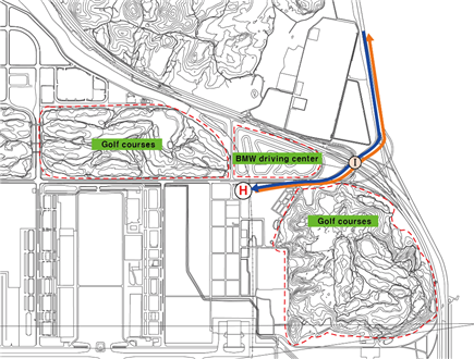
-
-
Special VFR flight for taking off or landing may only be permitted except helicopters, when
-
The ground visibility is not less than 1 500 m.
-
If ground visibility is not reported at airport, flight visibility is not less than 1 500 m (transition).
-
-
For Special VFR operations, the pilot shall :
-
fly only within control zone as cleared by Incheon Tower.
-
remain clear of clouds.
-
maintain at least 1 500 m of flight visibility.
-
maintain visual reference with surface or water.
-
Special VFR may be permitted only between sunrise and sunset unless the pilot is instrument rated and the aircraft is equipped for IFR flight in accordance with the requirement specified in civil aeronautics law.
(Except helicopters)
-
1) Squawk 7600
2) Continue to fly in VMC
3) Land at nearest suitable aerodrome
1) Squawk 7600, and
2) If able to see the light gun signal from control tower, follow that instruction
3) If unable to see the light gun signal from control tower, hold over downwind for RWY 16R/34L, 15L/33R until ETA or for 10 minutes, whichever is longer; then
4) land on RWY 16R/34L, 15L/33R or H in use as appropriate.
1) Squawk 7600
2) Maintain the last assigned speed and level, or minimum flight altitude if higher, for a period of 7 minutes following:
-
the time the transponder is set to Code 7600; or
-
the time the last assigned level or minimum flight altitude is reached;
whichever is later and thereafter adjust level and speed in accordance with the filed flight plan;
3) When being vectored or having been directed by ATC, proceed in the most direct manner possible to rejoin the current flight plan route no later than the next significant point, taking into consideration the applicable minimum flight altitude;
1) Squawk 7600
2) Follow the STAR issued by ATC. When being vectored or having been directed by ATC, proceed in the most direct manner possible to join the STAR(1.5 Assignment of STAR notified at RKSI AD 2.22 Flight Procedures) no later than the next significant point. Then commence descent as filed.
3) Start approach to the assigned runway without delay.
4) If no specific runway for landing has been assigned, start approach to runway 15L/33R without delay. If runway 15L/33R is closed, start approach to runway 15R/33L or runway 16R/34L.
* No fly area : The aircraft shall not fly north of R 271 YJU, except simultaneous approach RWY 15L/R aircraft.
|
Facilities |
RWY |
3 RVR REQ |
REDL & RCLL |
REDL &RCL*** |
REDL or RCL*** |
NIL (Day Only) | ||
|
TGS*, HIRL & RCLL |
HIRL & RCLL |
REDL & RCLL | ||||||
|
RVR / VIS** | ||||||||
|
Multi- Engine ACFT |
15L |
75 m / 300 ft |
125 m / 400 ft |
150 m / 500 ft |
200 m / 600 ft |
300 m / 1 000 ft |
400 m / 1 200 ft |
500 m / 1 600 ft |
|
33R |
75 m / 300 ft |
125 m / 400 ft |
150 m / 500 ft |
200 m / 600 ft |
300 m / 1 000 ft |
400 m / 1 200 ft |
500 m / 1 600 ft | |
|
15R |
75 m / 300 ft |
125 m / 400 ft |
150 m / 500 ft |
200 m / 600 ft |
300 m / 1 000 ft |
400 m / 1 200 ft |
500 m / 1 600 ft | |
|
33L |
75 m / 300 ft |
125 m / 400 ft |
150 m / 500 ft |
200 m / 600 ft |
300 m / 1 000 ft |
400 m / 1 200 ft |
500 m / 1 600 ft | |
|
16L |
75 m / 300 ft |
125 m / 400 ft |
150 m / 500 ft |
200 m / 600 ft |
300 m / 1 000 ft |
400 m / 1 200 ft |
500 m / 1 600 ft | |
|
34R |
75 m / 300 ft |
125 m / 400 ft |
150 m / 500 ft |
200 m / 600 ft |
300 m / 1 000 ft |
400 m / 1 200 ft |
500 m / 1 600 ft | |
|
16R |
75 m / 300 ft |
125 m / 400 ft |
150 m / 500 ft |
200 m / 600 ft |
300 m / 1 000 ft |
400 m / 1 200 ft |
500 m / 1 600 ft | |
|
34L |
75 m / 300 ft |
125 m / 400 ft |
150 m / 500 ft |
200 m / 600 ft |
300 m / 1 000 ft |
400 m / 1 200 ft |
500 m / 1 600 ft | |
Note : SIDs are designed in accordance with STANDARDS for FLIGHT PROCEDURE DESIGN.
* With certified TGS(Take-off Guidance System).
** The TDZ RVR/VIS may be assessed by the pilot.
*** For Night Operations at least REDL or RCLL and RENL are available.
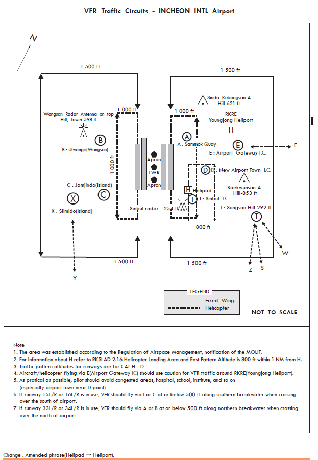
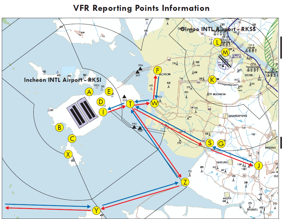
|
Reporting Point |
Geographical Name |
Position |
Coordinates(WGS-84) |
|---|---|---|---|
|
A |
Sammok Quay |
2.3 NM NE of Incheon R 084 NCN/D1.1 |
372959N 1262713E |
|
B |
Ulwangri |
2.9 NM SW of Incheon R 230 NCN/D3.5 |
372709N 1262251E |
|
C |
Jamjindo(Island) |
2.9 NM SW of Incheon R 197 NCN/D4.6 |
372505N 1262451E |
|
D |
New Airport Town IC |
2.7 NM E of Incheon R 112 NCN/D3 |
372859N 1262924E |
|
E |
Airport Gateway IC |
4.0 NM ENE of Incheon R 087 NCN/D4 |
373021N 1263024E |
|
F |
Buk-Incheon IC |
10.3 NM NE of Incheon R 076 NCN/D10 R 277 KIP/D8.2 |
373319N 1263713E |
|
G |
Eco Park |
10.0 NM S of Gimpo R 194 KIP/D9.8 |
372338N 1264622E |
|
I |
Sinbul IC |
2.3 NM SE of Incheon R 137 NCN/D3.6 |
372725N 1262923E |
|
J |
Jonam JCT |
11.7 NM SSE of Gimpo R 169 KIP/D12 |
372213N 1265206E |
|
K |
Kilo(Seoun JCT) |
3.0 NM SW of Gimpo R 231 KIP/D3 |
373125N 1264506E |
|
L |
Gimpoara Bridge |
2.2 NM N of Gimpo R 358 KIP/D2.1 |
373533N 1264700E |
|
M |
North Farmland of Gimpo Airport |
0.7 NM NNE of Gimpo R 014 KIP/D0.7 |
373408N 1264737E |
|
S |
Sorae |
10.0 NM SSW of Gimpo R 201 KIP/D10 |
372340N 1264439E |
|
T |
Songsan(Hill) |
5.7 NM E of Incheon R 106 NCN/D6 |
372853N 1263319E |
|
W |
Wolmido(Island) |
10.9 NM SSE of Gimpo R 248 KIP/D10.8 R 108 NCN/D8.2 |
372810N 1263553E |
|
X |
Silmido(Island) |
4.2 NM SW of Incheon R 207 NCN/D5.8 |
372415N 1262325E |
|
Y |
Younghungdo(Island) |
10.6 NM S of Incheon R 180 NCN/D12.6 |
371715N 1262800E |
|
Z |
Sihwa Breakwater |
14.2 NM SE of Incheon R 137 NCN/D15.7 |
372000N 1264120E |
RKSI AD 2.23 ADDITIONAL INFORMATION
-
Duration: March to November.
-
Type of maintenance :
Mowing the lawn, weeding, watering, and blight and harmful insects prevention.
-
Area affected.
All green areas within Movement Area.
Maintenance work shall be conducted only when 4 000 m or more of visibility is secured.
1) Area 1
-
- Dimension : Area of 60 m width from runway edge.
-
- Working hour : At midnight only when there are few aircraft movements.
2) Area 2
-
- Dimension : Other green area (including taxiways) except "Area 1".
-
- Working hour : During the day time only.
-
-
Remarks
All working vehicles within the maneuvering area shall be under control of Air Traffic Control, and aircraft in operation shall be under precaution.
-
Bird migration occurs during spring, fall and winter periods. The greatest degree of activity is observed during the following periods : whole of March ~ end of April(Spring migration), e arly of October ~ early December(winter migration). Weather conditions may affect bird migration on movements during different periods of the year
-
Spring and Autumn
In this period a large flock of birds, especially shorebirds is resting on the remnant of mudflats at high tide. And at low tide they are moving and scattered to forage their foods. Most of their movement flight is occurred on the ground surface or below about 200 ft.
The population of shorebirds reaches approximately 6 000 at one time in spring. Generally the number of birds is more in spring than autumn but on the contrary in the vicinity of airport bird activity is more frequent in autumn.
-
Winter
There are two ponds that are located respectively NW & SW of airport at the distance of about 4 KM from the runway.
Most of ducks inhabit at these ponds in winter and the flock size of one site is less than 400 individuals. The largest group of birds are Coots and about 1 000. These use this pond as resting site and only a few species feeds in the water. The movement of ducks is not related the tide and they are flying low (200 ft) to sea around the pond.
-
In order to reduce the wildlife hazard in the vicinity of runway wildlife control activities are being lasted 24h and include siren, threat of shotgun, visual scares and habitat managements. On the properties of airport farming, garbage treatment facilities are not permitted.
-
Hours of operation : H24
-
ARS telephone number : 82-32-743-2676
-
Telephone service is reference only. For the flight operation, use ATIS on the FREQ
-
- ARR : 128.4, 230.25 MHz
-
- DEP : 128.65, 344.2 MHz
-
-
SKY72 Golf Club and Dream Golf Range (GOLF CLUB & GOLF RANGE)
-
Duration : From April to December
-
Operation time schedule : 1930 ~ 2130 and 1000 ~ 1530 (UTC)
-
-
Orange Dunes YeongJong Golf Club (GOLF CLUB2)
-
Duration : From April to November
-
Operation time schedule : 1000 ~ 1530 (UTC)
-
-
Diagram

-
Operation time schedule
-
March to May : 0930 ~ 1400 (UTC)
-
June to September : 1000 ~ 1500 (UTC)
-
October to February : 0830 ~ 1400 (UTC)
-
-
Facility : Cable stayed bridge and pylon
-
Lamp color(1 KW, 2 KW) : White
-
Luminous : 1 KW(40 cd/㎡), 2 KW(60~70 cd/㎡)
-
Diagram

RKSI AD 2.24 CHARTS RELATED TO THE AERODROME

RKSI AD 2.25 VISUAL SEGMENT SURFACE(VSS) PENETRATION
NIL