RKSS — Gimpo
RKSS AD 2.1 AERODROME LOCATION INDICATOR AND NAME
RKSS - SEOUL / GIMPO International
RKSS AD 2.2 AERODROME GEOGRAPHICAL AND ADMINISTRATIVE DATA
| 1 |
ARP coordinates and site at AD |
373325N1264751E 328° / 1 327 m from THR 32R |
| 2 |
Direction and distance from city |
275°, 16 km from Seoul City Hall |
| 3 |
Elevation/Reference temperature |
18 m / 30.8°C |
| 4 |
Geoid undulation at the AD ELEV PSN |
23 m |
| 5 |
MAG VAR/Annual change |
|
| 6 |
Aerodrome Operator, Address, Telephone, Telefax, AFS |
Post:
Gimpo Airport Office(Seoul Regional Office of Aviation)
Post:
78, Haneul-gil, Gangseo-gu, Seoul, 07505 Republic of Korea Tel: Tel: +82-2-2660-2145, 2147, 5754 Fax: Telefax: +82-2-2662-5083, 2662-0424 AFS: AFS: RKSSZPZX |
| 7 |
Types of traffic permitted(IFR/VFR) |
IFR/VFR |
| 8 |
Remarks |
NIL |
RKSS AD 2.3 OPERATIONAL HOURS
| 1 |
Aerodrome Operator |
2100-1400 UTC* |
| 2 |
Customs and Immigration |
HO |
| 3 |
Health and Sanitation |
HO |
| 4 |
AIS Briefing Office |
H24 |
| 5 |
ATS Reporting Office |
H24 |
| 6 |
MET Briefing Office |
H24 |
| 7 |
ATS |
H24 |
| 8 |
Fuelling |
HO |
| 9 |
Handling |
HO |
| 10 |
Security |
HO |
| 11 |
De-icing |
H24 |
| 12 |
Remarks |
* Take-off and landing is restricted from 1400 UTC to 2100 UTC due to noise abatement, except the conditions described in RKSS AD 2.20 item 1.5 |
RKSS AD 2.4 HANDLING SERVICES AND FACILITIES
| 1 |
Cargo handling facilities |
All modern facilities. |
| 2 |
Fuel/oil types |
Fuel : Aviation Turbin Fuel (Jet A-1) Aviation Gasolin (AV-gas 100LL) Oil : Turbo oil 2 380/2 389, Jet oil 254 |
| 3 |
Fuelling facilities/capacity |
Jet A-1 available by hydrant refueling on passenger, remote, cargo apron, at rate of 1 000 gpm. 10 aircraft can be fueled simultaneously, total amount of storage is 35 771 000 liters. No limitations at any time service available. |
| 4 |
De-icing facilities |
Available.(Refer to Aircraft Parking/Docking Chart) |
| 5 |
Hangar space for visiting aircraft |
Business Aircraft Hangar : 4 for class “C” aircraft |
| 6 |
Repair facilities for visiting aircraft |
Major and minor repairs by arrangement |
| 7 |
Remarks |
NIL |
RKSS AD 2.5 PASSENGER FACILITIES
| 1 |
Hotels |
In Seoul city. |
| 2 |
Restaurants |
At AD and in the city. |
| 3 |
Transportation |
Buses, taxies, subway and rental cars from the AD |
| 4 |
Medical Facilities |
Ambulance service available. 17 hospitals near the AD within 18 km. |
| 5 |
Bank and Post Office |
Bank available at airport. |
| 6 |
Tourist Office |
Available at airport. |
| 7 |
Remarks |
http://www.airport.co.kr/mbs/gimpo/ |
RKSS AD 2.6 RESCUE AND FIRE FIGHTING SERVICES
| 1 |
AD Category for fire fighting |
AD Category for fire fighting : CAT 10 |
| 2 |
Rescue equipment |
Note : * ARFF (Aircraft Rescue and Fire Fighting) ** AFFF (Aqueous Film Forming Foam) |
| 3 |
Capability for removal of disabled aircraft |
|
| 4 |
Remarks |
Aviation Fire-Fighting training facility
|
RKSS AD 2.7 SEASONAL AVAILABILITY-CLEARING
| 1 |
Type of clearing equipment |
|
| 2 |
Clearance priorities |
|
| 3 |
Remarks |
Snow clearance information promulgated by SNOWTAM |
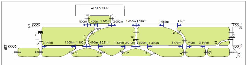
RKSS AD 2.8 APRONS, TAXIWAYS AND CHECK LOCATIONS / POSITION DATA
| 1 |
Designation, Surface and strength of aprons |
Surface - East & Central : Asphalt or Concrete - North & West : Concrete Strength - East & Central : PCN 74/F/B/X/T - North : PCN 67/R/B/W/T - West : PCN 58/R/B/W/T |
| 2 |
Designation, Width, surface and strength of taxiways |
Width - A, B2, C1 - C3, D2, D3, E1, E2, F2 : 35 m - B1, D1, G1, W1, W2, P : 30 m - F1 : 23 m - G2 : 40 m Surface : Asphalt or Concrete Strength - A, G2 : PCN 85/R/B/W/T - P : PCN 70/F/B/X/T(PCN 72/R/A/W/T: 1 096 m from SE TWY end/282 m from NW TWY end) - B1 : PCN 74/F/B/X/T(PCN 85/R/B/W/T : a partial of TWY, 270 m) - B2, C1, C2, C3, D1, D2, D3, E1, E2, F1, F2, G1, W1, W2 : PCN 74/F/B/X/T |
| 3 |
Location and elevation of altimeter checkpoint |
Central Apron : 16 m Other Aprons : 13 m |
| 4 |
VOR check points |
VOR : NIL |
| 5 |
INS check points |
INS: Refer to Aircraft Parking & Docking Chart |
| 6 |
Remarks |
NIL |
RKSS AD 2.9 SURFACE MOVEMENT GUIDANCE AND CONTROL SYSTEM AND MARKINGS
| 1 |
Use of Mode S transponder on the ground |
|
| 1.1 |
General |
This system using Mode S transponder improves the accuracy and the reliability of the ground movement monitoring system |
| 1.2 |
ACFT equipped with Mode S transponder |
ACFT operators shall ensure that Mode S transponders are able to operate when ACFT is on the ground |
| 1.2.1 |
Departing ACFT(Including ACFT that require de-icing) |
Prior to push-back or taxiing from a parking stand whichever comes first: - Enter, using either FMS mod or transponder control unit, the flight identification as specified in item 7 of the ICAO flight plan(ex:KAL123, AAR456) or enter in the absence of flight identification, the ACFT registration. - Select XPNDR or its equivalent in relation to specifications on the installed model. - If function is available, select AUTO mode. - Do not select Off or STBY functions. - Set Mode A code assigned by ATC. Lining up - select TA/RA |
| 1.2.2 |
Arriving ACFT |
After landing and until the ACFT is stationary at parking stand: - Maintain XPNDR or its equivalent in relation of specification of the installed model. - Do not select OFF and STBY functions. - Maintain Mode A code assigned by ATC When ACFT is staionary at the parking stand, select OFF or STBY. |
| 1.2.3 |
Other cases of taxiing ACFT(including toeing ACFT) |
Select XPNDR or its equivalent in relation to specifications of the installed model. - If function is available, select AUTO mode. Do not select OFF and STBY functions. Set Mode A code to 2000 |
| 1.3 |
ACFT not equipped with Mode S transponder or with an unserviceable Mode S transponder |
Departing ACFT: - Maintain Mode A+C transponder in the ON position until lining up. Arriving ACFT: - Maintain Mode A+C transponder in the On positon and Mode A code assigned by ATC until parking stand. Other cases of taxiing ACFT: - Select A+C transponder in the On position or its equivalent in relation to specifications of the installed model. - Do not select of OFF and STBY function. - Set Mode A code to 2000 Fully parked on stand - Select OFF or STBY position |
| 2 |
Use of aircraft stand ID signs, TWY guide lines and visual docking/parking guidance system of aircraft stands |
Taxiing guidance signs at all intersections with TWY, RWY and at all holding positions. Guide lines at apron. Nose-in guidance at aircraft stands. Visual docking guidance system : NIL |
| 3 |
RWY and TWY markings and LGTs |
RWY - Lights RWY 14L/32R - Edge, THR, End, TDZ RWY 14R - Edge, THR, End, CL, TDZ RWY 32L - Edge, THR, End, CL - Marking RWY 14L/32R - Designation, THR, TDZ, Center Line,Side Strip, Aiming point marked RWY 14R/32L - Designation, THR, TDZ, Center Line, Side Strip, Aiming point marked. TWY - Lights TWY edge lights - All TWY TWY CL lights - All TWY (except : W1, W2 , F1, Part of R(P1~NR 121) ) * TWY CL lights are not installed on the parts of the taxi routes crossing over RWY 14L/32R, but are newly installed only BTN TWY B1 and B2, TWY G1 and G2 , TWY C1 and C2, TWY E1 and E2 . - Marking TWY & taxilane centerline marked Holding positions at all TWY/RWY intersections marked |
| 4 |
Stop bars |
Refer to Aerodrome Ground Movement Chart |
| 5 |
Remarks |
NIL |
RKSS AD 2.10 AERODROME OBSTACLES
| In Area 2 |
|||||
| OBST ID/ Designation |
OBST type |
OBST position |
ELEV/HGT |
Markings/ Type, colour |
Remarks |
| a |
b |
c |
d |
e |
f |
| RKSSOB001 |
Mt. Gwanak(Electric Tower) |
372642.5N 1265750.5E |
2 287 ft/2 228 ft |
LGTD |
32L/R APCH |
| RKSSOB002 |
Mt. Samsung(North Peak) |
372652.0N 1265551.4E |
1 348 ft/1 289 ft |
NIL |
14L/R TKOF |
| RKSSOB003 |
BLDG. Sinturi |
373046.2N 1265112.9E |
283 ft/224 ft |
NIL |
|
| RKSSOB004 |
Mt. Samsung(South Peak) |
372609.4N 1265621.8E |
1 578 ft/1 519 ft |
NIL |
|
| RKSSOB005 |
Mt. Samsung(Transmitting Tower) |
372559.6N 1265629.3E |
1 742 ft/1 683 ft |
LGTD |
|
| RKSSOB006 |
BLDG. Yangcheon Middle School |
373110.6N 1264932.9E |
413 ft/354 ft |
NIL |
|
| RKSSOB007 |
BLDG. Gwangyeong girl's High School |
373217.0N 1264924.4E |
180 ft/121 ft |
NIL |
|
| RKSSOB008 |
Temple(Daegaksa) |
373028.8N 1264929.5E |
453 ft/394 ft |
NIL |
|
| RKSSOB009 |
BLDG. Mokdong |
373138.2N 1265232.7E |
891 ft/832 ft |
LGTD |
|
| RKSSOB010 |
Mt. Jangneong |
373658.6N 1264233.1E |
493 ft/434 ft |
NIL |
14L/R APCH |
| RKSSOB011 |
Hill. Daejun |
373522.9N 1264527.5E |
123 ft/64 ft |
NIL |
32L/R TKOF |
| RKSSOB012 |
Mt. Gaeyang (Transmitting Tower) |
373311.0N 1264252.6E |
1 506 ft/1 447 ft |
LGTD |
|
| RKSSOB013 |
Mt. Gahyun |
373732.9N 1263902.6E |
706 ft/647 ft |
NIL |
|
| In Area 3 |
|||||
| OBST ID/ Designation |
OBST type |
OBST position |
ELEV/HGT |
Markings/ Type, colour |
Remarks |
| a |
b |
c |
d |
e |
f |
| RKSSOB0014 |
HF antenna |
373311.0N 1264706.0E |
103 ft/44 ft |
LGTD |
|
RKSS AD 2.11 METEOROLOGICAL INFORMATION PROVIDED
| 1 |
Associated MET Office |
Gimpo Airport Weather Office ∙ TEL : +82-2-2664-0365 ∙ FAX : +82-2-2664-0366 |
| 2 |
Hours of service MET Office outside hours |
24 hours - |
| 3 |
Office responsible for TAF preparation Periods of validity |
Gimpo Airport Weather Office 30 hours at 0000, 0600, 1200, 1800 UTC |
| 4 |
Trend forecast Interval of issuance |
Trend Type forecast 1 hour (METAR) and when SPECI reported |
| 5 |
Briefing/consultation provided |
Available at the Office for 24 hours, if required |
| 6 |
Flight documentation language(s) used |
Aerodrome forecasts (TAF code form), SIGWX charts, WINTEM charts, SIGMET information in English |
| 7 |
Charts and other information available for briefing or consultation |
Analysis charts (surface and upper air), Prognostic charts, Graphic displays and other model outputs |
| 8 |
Supplementary equipment available for providing information |
Satellite and Weather radar imageries |
| 9 |
ATS units provided with information |
|
| 10 |
Additional informaton |
All observation data, model outputs and forecasts produced by KMA and WAFS are available at the Office through Internet link. |
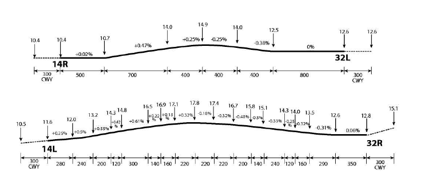
RKSS AD 2.12 RUNWAY PHYSICAL CHARACTERISTICS
| Designations Runway NR |
True bearing |
Dimension of RWY(M) |
Strength(PCN) and surface of RWY and SWY |
THR coordinates RWY end coordinates THR Geoid Undulation |
THR elevation and highest elevation of TDZ of precision APP RWY |
|---|---|---|---|---|---|
| 1 |
2 |
3 |
4 |
5 |
6 |
| 14R |
135.00° |
3 200 × 60 | 74/F/B/X/T Asphalt |
373406.19N 1264631.60E 373252.83N 1264803.71E GUND 22.9 M |
THR 10.4 M/34.1 FT TDZ 12.6 M/41.3 FT |
| 32L |
315.02° |
3 200 × 60 | 74/F/B/X/T Asphalt |
373252.83N 1264803.71E 373406.19N 1264631.60E GUND 22.9 M |
THR 12.6 M/41.3 FT TDZ 12.9 M/42.3 FT |
| 14L |
135.01° |
3 600 × 45 | - 74/F/B/X/T Asphalt - 85/R/B/W/T Concrete(156 m from RWY THR) |
373414.55N 1264641.80E 373251.89N 1264825.58E GUND 22.9 M |
THR 11.6 M/38.0 FT TDZ 15.1 M/49.5 FT |
| 32R |
315.03° |
3 600 × 45 | - 74/F/B/X/T Asphalt - 85/R/B/W/T Concrete (151 m from RWY THR) |
373251.89N 1264825.58E 373414.55N 1264641.80E GUND 23.0 M |
THR 12.8 M/41.9 FT TDZ 13.8 M/45.2 FT |
| 7. Slope of RWY-SWY |
|||||
|
|||||
| SWY dimensions(M) |
CWY dimensions(M) |
Strip dimensions(M) |
RESA dimensions(m) |
Location & description of arresting system |
OFZ |
||
|---|---|---|---|---|---|---|---|
| 8 |
9 |
10 |
11 | 12 | 13 |
||
| NIL |
300 × 300 300 × 300 |
3 320 × 300 |
259 × 150 250 × 150 |
NIL |
Conforms to the standards specified in ANNEX 14, Chapter 4. |
||
| NIL |
300 × 300 300 × 300 |
3 720 × 300 |
260 × 150 255 × 150 |
NIL |
|||
| 12. Remarks
|
|||||||
RKSS AD 2.13 DECLARED DISTANCES
| RWY Designator |
TORA (M) |
TODA (M) |
ASDA (M) |
LDA (M) |
Remarks |
|---|---|---|---|---|---|
| 1 |
2 |
3 |
4 |
5 |
6 |
| 14L 14L 14L 14L 14L 14L 14L 14L 14L |
3 600 3 144 2 775 2 010 2 010 1 824 1 190 1 190 1 000 |
3 900 3 444 3 075 2 310 2 310 2 124 1 490 1 490 1 300 |
3 600 3 144 2 775 2 010 2 010 1 824 1 190 1 190 1 000 |
3 600 - - - - - - - - |
Take-off from intersection with TWY G2 Take-off from intersection with TWY F2 Take-off from intersection with TWY E2 Take-off from intersection with TWY D3 Take-off from intersection with TWY D1 Take-off from intersection with TWY D2 Take-off from intersection with TWY C3 Take-off from intersection with TWY C1 Take-off from intersection with TWY C2 |
| 32R 32R 32R 32R 32R 32R 32R 32R 32R |
3 600 3 147 2 410 2 410 2 221 1 590 1 590 1 400 740 |
3 900 3 447 2 710 2 710 2 521 1 890 1 890 1 700 1 040 |
3 600 3 147 2 410 2 410 2 221 1 590 1 590 1 400 740 |
3 600 - - - - - - - - |
Take-off from intersection with TWY A Take-off from intersection with TWY B2 Take-off from intersection with TWY C2 Take-off from intersection with TWY C1 Take-off from intersection with TWY C3 Take-off from intersection with TWY D2 Take-off from intersection with TWY D1 Take-off from intersection with TWY D3 Take-off from intersection with TWY E1 |
| 14R 14R 14R 14R 14R 14R |
3 200 1 983 1 610 1 200 920 800 |
3 500 2 283 1 910 1 500 1 220 1 100 |
3 200 1 983 1 610 1 200 920 800 |
3 200 - - - - |
Take-off from intersection with TWY G1 Take-off from intersection with TWY E1 Take-off from intersection with TWY D1 Take-off from intersection with TWY W2 Take-off from intersection with TWY C1 Take-off from intersection with TWY W1 |
| 32L 32L 32L 32L 32L 32L |
3 200 2 400 2 000 2 000 1 590 914 |
3 500 2 700 2 300 2 300 1 890 1 214 |
3 200 2 400 2 000 2 000 1 590 914 |
3 200 - - - - |
Take-off from intersection with TWY B1 Take-off from intersection with TWY W1 Take-off from intersection with TWY C1 Take-off from intersection with TWY W2 Take-off from intersection with TWY D1 Take-off from intersection with TWY E1 |
RKSS AD 2.14 APPROACH AND RUNWAY LIGHTING
| RWY |
APCH LGT type LEN INTST |
THR LGT Colour WBAR |
VASIS (MEHT) PAPI |
TDZ, LGT LEN |
RWY Center Line LGT Length, Spacing Colour, INTST |
RWY edge LGT LEN,Spacing Colour INTST |
RWY End LGT Colour WBAR |
SWY LGT LEN(M) Colour |
Remarks |
|---|---|---|---|---|---|---|---|---|---|
| 1 |
2 |
3 |
4 |
5 |
6 |
7 |
8 |
9 |
10 |
| 32R |
ALSF-II 900 M LIH |
Green - |
PAPI Left/3° |
900 M |
NIL |
3 600 M 60 M White/Yellow LIH |
Red - |
NIL |
NIL |
| 14L |
ALSF-II 900 M LIH |
Green - |
PAPI left/3° |
900 M |
NIL |
3 600 M 60 M white/Yellow LIH |
Red - |
NIL |
NIL |
| 32L |
ALSF-I 750 M LIH |
Green - |
PAPI Left/3° |
NIL |
3 200 M 15 M White/Red LIH |
3 200 M 60 M White/Yellow LIH |
Red - |
NIL |
NIL |
| 14R |
ALSF-II 900 M LIH |
Green - |
PAPI Left/3° |
900 M |
3 200 M 15 M White/Red LIH |
3 200 M 60 M White/Yellow LIH |
Red - |
NIL |
NIL |
RKSS AD 2.15 OTHER LIGHTING, SECONDARY POWER SUPPLY
| 1 |
ABN/IBN location, characteristics and hours of operation |
ABN : At old tower FLG W & G EV 2.5SEC/ IBN : NIL H24 |
| 2 |
LDI location and lighting Anemometer location and lighting |
LDI : NIL Anemometer : NIL |
| 3 |
TWY edge and center line lighting |
Edge line : All TWY (except : W1, W2, Part of R(P1~NR 121)) * TWY CL lights are not installed on the parts of the taxi routes crossing over RWY 14L/32R, but are newly installed only BTN TWY B1 and B2, TWY G1 and G2, TWY C1 and C2, TWY E1 and E2. |
| 4 |
Secondary power supply/swithch-over time |
Secondary power supply to all lighting at AD Switch-over time: 1 or 15 SEC according to kind of lights (Complied with ICAO requirements) |
| 5 |
Remarks |
NIL |
RKSS AD 2.16 HELICOPTER LANDING AREA
| 1 |
Coordinates TLOF or THR of FATO |
- |
| 2 |
TLOF and/or FATO elevation |
- |
| 3 |
TLOF and FATO area dimensions, surface, strength, marking |
- |
| 4 |
True and MAG BRG of FATO |
- |
| 5 |
Declared distance available |
- |
| 6 |
APP and FATO lightng |
- |
| 7 |
Remarks |
As directed by ATC |
RKSS AD 2.17 ATS AIRSPACE
| 1 |
Designation and lateral limit |
Gimpo CTR; A circle, radius 5 NM centered at (ARP) |
| 2 |
Vertical limits |
SFC to 3 000 FT AGL |
| 3 |
Airspace classification |
B |
| 4 |
ATS unit call sign Language(s) |
GIMPO Tower English / Korean |
| 5 |
Transition altitude |
14 000 FT AMSL |
| 6 |
Operational hours |
H24 |
| 7 |
Remarks |
NIL |
RKSS AD 2.18 ATS COMMUNICATION FACILITIES
| Service designation |
Call sign |
Frequency |
Hours of operation |
Remarks |
|---|---|---|---|---|
| 1 |
2 |
3 |
4 |
5 |
| TWR |
Gimpo Tower |
118.1 MHz* 118.05 MHz** 240.9 MHz* |
H24 |
NIL |
| GND |
Gimpo Ground |
121.9 MHz* 121.95 MHz** |
H24 |
NIL |
| Delivery |
Gimpo Delivery |
121.975 MHz** |
H24 |
Digital PDC service Available |
| ATIS |
Gimpo INTL Airport |
126.4 MHz** 317.8 MHz* |
H24 |
1. Digital ATIS service Available 2. ATIS telephone service available. (Refer to RKSS AD 2-31 for detail) |
| APP |
Seoul Approach |
119.05 MHz** 119.75 MHz** 119.1 MHz* 119.9 MHz* 120.8 MHz** 121.35 MHz* 124.2 MHz** 293.3 MHz** 305.7 MHz* |
H24 |
NIL |
| VFR |
123.25 MHz** 123.8 MHz* 363.8 MHz** |
|||
| DEP |
Seoul Departure |
121.4 MHz** 124.8 MHz* 125.15 MHz** 353.2 MHz* |
H24 |
NIL |
| EMERG |
121.5 MHz* 243.0 MHz** |
H24 |
NIL |
|
| Scheduled Inspection Time : - * : Every 1st THU(1500-2000 UTC) of the month - ** : Every 3rd THU(1500-2000 UTC) of the month |
||||
RKSS AD 2.19 RADIO NAVIGATION AND LANDING AIDS
| Type of aid, MAG VAR, Type of supperted OPS |
ID |
Frequency |
Hours of operation |
Position of transmitting antenna coordinates |
Elevation of DME transmitting antenna |
Remarks |
|---|---|---|---|---|---|---|
| 1 |
2 |
3 |
4 |
5 |
6 |
7 |
| VOR/DME |
KIP |
113.60 MHz (CH 83X) |
H24 |
373327.1N 1264731.3E |
30 m |
VOR/DME unuse : RDL 331 clockwise RDL 360, RDL 001 clockwise RDL 099 not flight checked RDL 270 clockwise RDL 278 beyond 15 NM below 3 500 ft AMSL RDL 290 clockwise RDL 310 beyond 15 NM due to RK P518 RDL 311 clockwise RDL 330 beyond 12 NM due to RK P518 Scheduled Inspection time: Every 2nd TUE(1500-1800 UTC) of the month. |
| LOC 14R ILS CAT II/III |
IOFR |
108.70 MHz |
H24 |
373245.5N 1264812.9E |
- |
RWY 14R LOC unusable beyond 12 NM FM GP-DME and beyond 10° Left side of the course not flight check due to RK P518 Scheduled Inspection time: Every 1st THU (1400-1900 UTC) of the month |
| GP 14R |
- |
330.5 MHz |
H24 |
373401.8N 1264644.0E |
- |
Scheduled Inspection time: Every 1st THU (1400-1900 UTC) of the month |
| DME 14R |
IOFR |
985.0 MHz (CH 24X) |
H24 |
373401.9N 1264644.2E |
30 m |
|
| IM 14R |
- |
75 MHz |
H24 |
373413.7N 1264622.1E |
||
| LOC 14L ILS CAT I |
ISEL |
109.90 MHz |
H24 |
373244.6N 1264834.7E |
RWY 14L LOC unusable beyond 12 NM from GP-DME and beyond 10° Left side of the Course not flight check due to RK P518 Scheduled inspection time: Every 2nd THU(1400 - 1900 UTC) of the month |
|
| GP 14L |
- |
333.8 MHz |
H24 |
373403.9N 1264648.2E |
||
| DME 14L |
ISEL |
997 MHz (CH 36X) |
H24 |
373403.8N 1264648.1E |
30 m |
|
| IM 14L |
- |
75 MHz |
H24 |
373421.9N 1264632.6E |
||
| LOC 32R ILS CAT I |
ISKP |
110.70 MHz |
H24 |
373421.7N 1264632.8E |
RWY 32R LOC unusable beyond 10° Right side of the Course not flight check due to RK P73A/B Scheduled inspection time: Every 3rd THU (1400-1900UTC) of the month |
|
| DME 32R |
ISKP |
1005 MHz (CH 44X) |
H24 |
373256.3N 1264812.9E |
30 m |
|
| GP 32R |
- |
330.2 MHz |
H24 |
373256.4N 1264813.1E |
||
| IM 32R |
- |
75 MHz |
H24 |
373244.5N 1264834.9E |
||
| LOC 32L ILS CAT I |
IKMO |
108.30 MHz |
H24 |
373413.4N 1264622.6E |
RWY 32L LOC unusable beyond 12° NE side of the course due to RK P73 Scheduled inspection time: Every 4th THU(1400-1900UTC) of the month Scheduled inspection time: Every 4th THU (1400-1900UTC) of the month |
|
| DME 32L |
IKMO |
981 MHz (CH 20X) |
H24 |
373257.2N 1264751.2E |
30 m |
Scheduled inspection time: Every 4th THU (1400-1900UTC) of the month |
| GP 32L |
334.1 MHz |
H24 |
373257.3N 1264751.2E |
|||
| VORTAC (8°W/2015) |
SEL |
115.5 MHz (CH102) |
H24 |
372449.0N 1265542.1E |
900 ft |
See ENR 4.1 for the details |
| VOR/DME (Yangju) |
YJU |
114.90 MHz (CH 96X) |
H24 |
374453N 1265928E |
VOR/DME Unuseable : RDL 081 clockwise RDL 100 beyond 20 NM not flight check due to RK P518 RDL 125 clockwise RDL 155 beyond 30 NM due to RK R17 RDL 155 clockwise RDL 220 not flight check due to RK P73A/73B RDL 250 clockwise RDL 265 beyond 30 NM not flight check due to RK P518 RDL 265 clockwise RDL 271 beyond 20 NM not flight check due to RK P518 RDL 271 clockwise RDL 081 not flight check due to RK P518 |
|
| Scheduled Inspection Time ASDE : Every 3rd TUE(0100~0800 UTC) of the month when visibility is at or above 5 km(VMC). RADAR (PSR, SSR) : Every 2nd, 4th WED (1400~1900 UTC) of the month. SEL(VORTAC) : Every 3rd TUE (1500~2000 UTC) of the month. Yangju(VOR/DME) : Every 2nd WED (1500-2000 UTC) of the month. |
||||||
RKSS AD 2.20 LOCAL AERODROME REGULATIONS
1 Airport regulations
Aircraft on international flight may be permitted to use the Gimpo Airport (RKSS) under the following conditions;
-
Aircraft
-
Private aircraft which is owned by an enterprise or a person, except the following aircraft;
1) public charter which is not scheduled,
2) Inclusive tour charter,
3) aircraft having a seating capacity of more than 50 passengers
4) aircraft having a maximum payload capacity of 2 721 kg (6 000 lbs) or more,
5) aircraft carrying commercial goods (including free-of-charge carriage), or
6) state aircraft which is not owned by an enterprise or a person
-
Ferry-flight of an aircraft which is Korean-registered and internationally operating for the purpose of import, maintenance or charter flight support
-
-
Restriction
The use of the Gimpo Airport may not be permitted when required for certain reasons, including the shortage of airport capacity, safety or security.
-
Permitted Hours : 2100-1400 UTC, daily (In other hours, the Incheon International Airport or the other airports should be used)
-
Landing to RWY(14R/32L)
-
Recommendation for increase RWY(14R/32L) operation capacity, except for wet or contaminated:
recommend to use Rapid Exit Taxiways and fully vacate within 60 seconds after touchdown.
-
If possible, maintain speed at or above 30 kt IAS until reaching Rapid Exit Taxiway ‘C1’ or ‘E1’
RWY
RET
Taxi Procedure
Distance from Threshold
14R
C1
After landing, vacate via C1 then hold short of RWY 14L.
Remain on the TWR frequency.
6 397 ft/1 950 m
32L
E1
After landing, vacate via E1 then hold short of RWY 32R.
Remain on the TWR frequency.
6 512 ft/1 985 m
-
-
Landing to RWY(14L/32R)
Unless otherwise cleared by ATC, aircrafts are advised to vacate RWY as follow;
RWY
RET
Taxi Procedure
32R
D3
After landing, vacate via D3. When vacating RWY, contact GND frequency.
14L
C2
After landing, vacate via C2. When vacating RWY, contact GND frequency.
* If unable to follow the above RWY vacating routes, pilots should notify it to ATC.
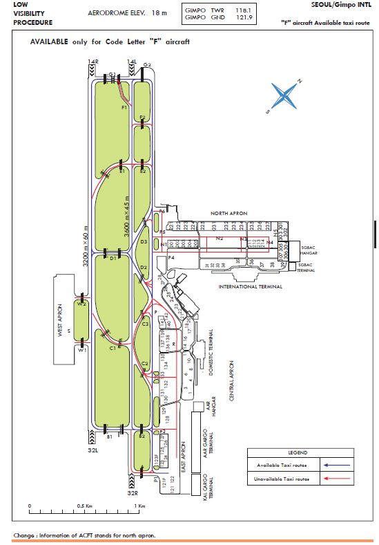
| Taxiway |
B1, B2, D1, D2, D3, G1, G2, P |
Up to code letter "F" available ※ Refer to RKSS AD 2-22 |
| A, C1, C2, C3, E1, E2, F1, F2 |
Up to code letter "E" available |
|
| W1, W2 |
Up to code letter "B" available |
|
| Taxilane |
P1 |
Up to code letter "F" available |
| N1, N2, N3, N4, P2, P3, P4, P5, P6, R |
Up to code letter "E" available |
|
| T, S |
Up to code letter "B" available |
|
| N5 |
Up to code letter "C" available |
| Runway |
14R/32L, 14L/32R |
None |
| Taxiway |
B1, B2, C1, C2, C3, D1, D2, D3, E1, E2, F1, F2, G1, W1, W2 |
None |
| A,G2,P |
B787-900 (Up to 240 413 kg) |
|
| Taxilane |
P1, P2, P3, P4, P5, P6, N1, N2, N3, N4, N5, R |
B787-900 (Up to 240 413 kg) |
| Apron |
East, Central |
None |
| North |
B787-900 (Up to 240 413 kg) |
All general aviation aircraft(fixed & rotary wing) operator who plans to fly to Gimpo International Airport should contact with airport operator (airside operations team) at least 1 day before the flight (before filing flight plan), to confirm aircraft stand availability.
Contact : +82-2-2660-2566~7
-
All training flights are prohibited at Gimpo Airport, except for turbofan engine aircraft. The deliberate simulation of engine failure is not permitted whilst on approach to or departure from the airport.
-
The use of this airport by light sports aircraft, ultra-light vehicles and lighter than air is prohibited.
2 Ground Procedure
2.1 Radio frequency change points
Departure-
RWY 14L/R in use
Aircraft taxiing on TWY P shall change to and monitor 118.1 MHz(Gimpo TWR) abeam TWY "E2" unless otherwise instructed by ATC.
-
RWY 32R/L in use
Aircraft taxiing on TWY P shall change to and monitor 118.1 MHz(Gimpo TWR) abeam TWY "C2“ or entering Taxilanes P1, P2 or P3 unless otherwise instructed by ATC.
Arrival
Aircraft shall change radio frequency from Gimpo Tower (118.1 MHz) to Gimpo Ground (121.9 MHz) when entering "P" taxiway from runway.
* Note : After landing on the RWY 14R or RWY 32L, do not change to GND FREQ until vacating both RWY unless otherwise instructed by ATC.
-
All aircraft should taxi at speeds of more than 10 kt on Taxiway P to ensure smooth traffic flow unless there is an exceptional direction for safety reason by ATC. And if it is impracticable, pilots shall notify ATC.
-
All the class E aircraft including B747 holding on TWY B1 for RWY 32L departure should maintain engine power at ground idle so that the landing traffic on RWY 32R are protected from the jet blast.
-
All Aircraft on P5 should wait at the waiting point on P5 if N1, N2, N3 or N4 is occupied by any aircraft.
-
Aircraft waiting on N1 for deicing or for other purposes should stop at the stop line, and a marshal should maintain radio communication with ATC.
-
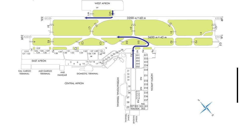
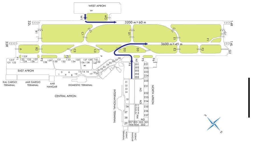
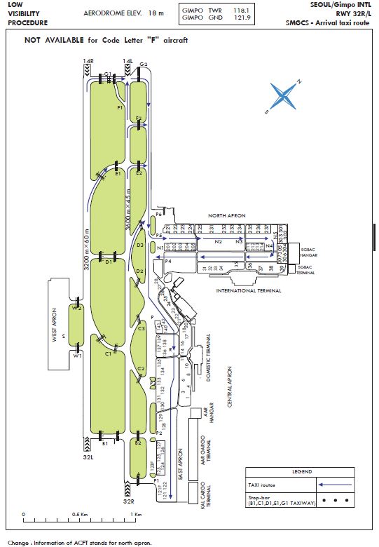
Standard taxi procedures for north apron
Unless otherwise cleared by ATC, taxi into and out of north apron as follows;
〔Caution〕While taxiing to/from the International Terminal via P4 or P5, pilots should look out for other aircraft that might be holding on taxiway N1, N2 and N3 in order to avoid collision risk.
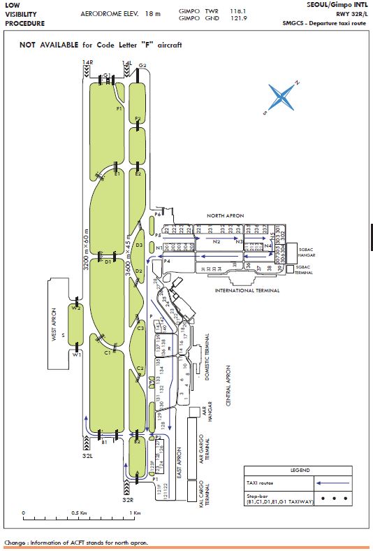
Departure
-
Aircraft stands from NR. 31 to 34 proceed to "P" TWY via "P4" TWY.
-
Aircraft Stands from NR. 35 to 39, NR. 201 to 205, NR. 211 to 214 and NR. 304 to 307 proceed to "P" TWY via "P4" TWY.
-
Aircraft Stands from NR. 221 to 225, proceed to "P" TWY via "N2" and "P4" TWY.
-
Aircraft Stands from NR. 231 to 237, NR. 301 to 303, proceed to "P" TWY via "N4" and "P4" TWY.
Arrival
-
Aircraft stands from NR. 201 to 205, NR. 211 to 214, NR. 221 to 225 and NR. 231 to 237 From "P" TWY, proceed to aircraft stand via "P5" TWY.
-
Aircraft Stands from NR. 31 to NR. 34 From "P" TWY, proceed to aircraft stand via "P5" and "N3" TWY.
-
Aircraft Stands from NR. 301 to NR. 303 From "P" TWY, proceed to aircraft stand via "P5" and "N5" TWY.
-
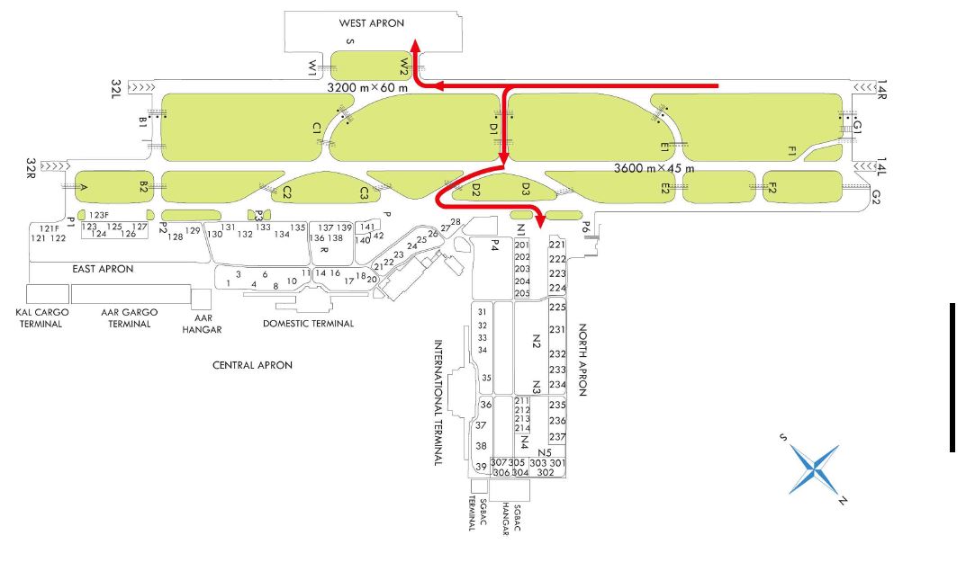
All aircraft within the west apron shall be operated in accordance with the following conditions.
-
An aircraft operating on the west apron shall not taxi, push-back or tow unless prior authorization has been obtained from the control tower.
-
Park at appropriate stands considering aircraft dimensions specified herein, all aircraft must be parked within the aircraft stand safety lines.
Refer to the AIRCRAFT PARKING/DOCKING CHART ICAO for the details
-
Wheeled helicopters are restricted to ground taxi only.
-
When any adjacent stand is occupied, power driven turn of aircraft at the stand is prohibited.
-
All stands are restricted to start-up only, and all engine run-up must be performed in designated area only.
-
Fixed-wing aircraft must be tied down when parking.
-
For helicopters, before commencing movement with self-power at stands(#922, #923 ) adjacent to fixed-wing stand, be sure that fixed-wing aircraft is tied down.
-
-
Standard Taxi Procedures
Unless otherwise cleared by ATC, the taxi procedures of the aircraft within the Apron are as follows.
-
Departure
1) Fixed-wing aircraft
-
a) stand → 'S' taxilane → TWY 'W1' or 'W2' → RWY
-
b) stand → 'T' taxilane → TWY 'W2' → RWY
2) For helicopter, proceed from the stand to H3 or H4 via "S" taxilane.
-
-
Arrival
1) Fixed-wing aircraft
-
a) RWY → TWY 'W1' → 'S' taxilane→ TWY 'W2' → 'T' taxilane → stand
-
b) RWY → TWY 'W2' → 'T' taxilane→ stand
2) For helicopter, proceed from the stand to H3 or H4 via "S" taxilane.
-
-
-
Radio Communication Procedures
Unless otherwise instructed by ATC, all aircraft should change radio frequency as follows.
-
Departure
1) Fixed-wing aircraft shall contact Gimpo Ground (121.9 MHz) on the stand before taxiing and contact Gimpo Tower (118.1 MHz) prior to entering TWY 'W1' or TWY 'W2' for take off.
2) Helicopters should contact Gimpo Ground (121.9 MHz) on the stand for taxiing and switch to Gimpo Tower (118.1 MHz) prior to entering "H3" or "H4" for take off.
-
Arrival
1) Fixed-wing aircraft should contact Gimpo Ground (121.9 MHz) just after entering “W1” or “W2” taxiway for ground taxi.
2) Helicopters should contact Gimpo Ground (121.9 MHz) prior to entering the “S” taxilane for taxiing, after landing "H3" or "H4".
-
-
The use of RUN-UP PAD
-
Hour of Operation : Available between 30 minutes after sunrise and 30 minutes before sunset
-
The use of RUN-UP PAD may be permitted only under prior approval obtained from the control tower.
-
A continuous communication with the control tower shall be maintained while using RUN-UP PAD.
-
No maintenance is permitted on RUN-UP PAD(except compulsory maintenance during RUN-UP).
-
Hover check is not available over run-up pad.
(But hover check at H3 or H4 will be available under ATC permission below 50 feet)
-
-
Restrictions
-
Any helicopter is not allowed to taxi on Taxiway 'W2' and taxilane 'T'
-
Any helicopter must follow the regular operating hours(within 1HR/MAX) when using spot #908-2 and spot #909. Layover is not permitted.
-
Any helicopter which are not registered in Gimpo INTL airport are not allowed to park more than 30 minutes when using stand 912. Layover is not permitted on the stand.
-
-
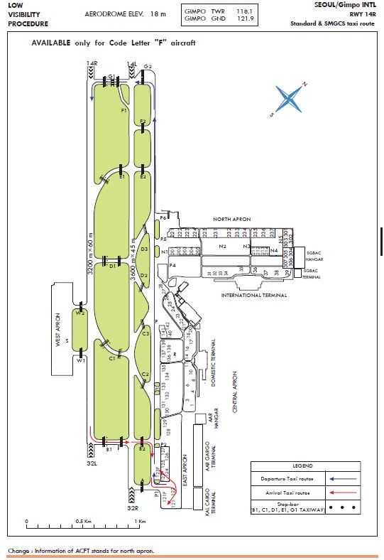
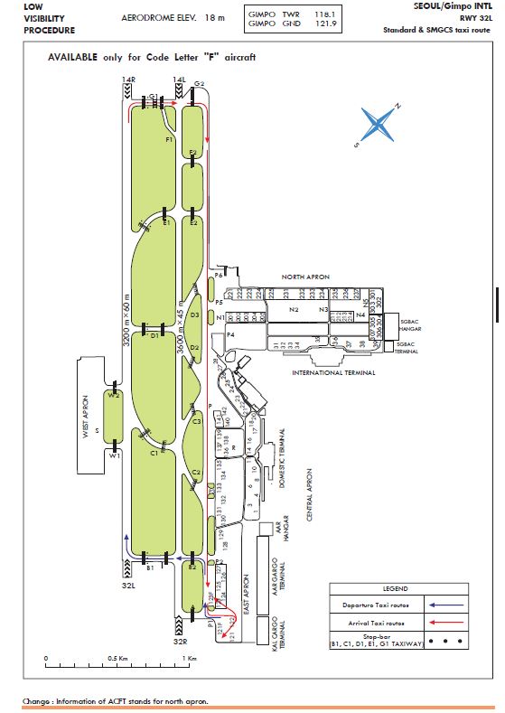
Taxiing procedures to and from NR 121F and 123F for both standard and low visibility operations are as follows :
-
Departure (Refer to RKSS AD 2-20, 2-21)
RWY 14R - 121F/123F → P1 → P → G2 → G1
RWY 32L - 121F123F → P1 → P → B2 → B1
-
Arrival (Refer to RKSS AD 2-20, 2-21)
RWY 14R - B1 → B2 → P → P1 → 121F/123F
RWY 32L - G1 → G2 → P → P1 → 121F/123F
-
-
Restriction
-
Take off or landing RWY 14L/32R shall be restricted, While A380 aircraft is occupying on "P" TWY.
-
Any Aircraft shall not enter TWY "N1", while "F" aircraft is occupying "P" TWY.
-
"F" aircraft requires Follow me car service and shall comply with the taxi speed limit 17 kt when taxi on park of "P" TWY from "P6" to "F2".
-
Push-back restriction on NR 121F : Nose-gear cannot cross over intermediate holding position marking on TWY 'R' behind the stand 123.
-
Push-back restriction on NR 123F : Nose-gear cannot cross over intermediate holding position marking on TWY ‘R’ behind the stand 122.
-
The aircraft, the code letter "F", are not able to take-off or land on RWY 14L/32R.
-
-
Some roadways for GSE (Ground Service Equipment) vehicle crossing P1, P2, P3 taxilane are marked in the form of zipper.
-
Pilots shall give an extra caution to the vehicles during taxiing because there are roadways for vehicle crossing R, P1, P2, P3, P4, P5 taxilane in the ramp.
-
Some of Code letter B aircraft stands(502, 503, 506~514) in West Apron don't provide minimum clearance distance(3 m) from apron safety line to tail of an aircraft. Any vehicle, equipment or person should obtain prior clearance from control tower.
-
Some of Code letter E aircraft stands (221~232) in North Apron do not provide minimum clearance distance(7.5 m) from apron safety line to tail of an aircraft. Any vehicle, equipment or person should obtain prior clearance from control tower.
-
Pilots should always operate transponders with XPNDR (and AUTO if available) except for parking ACFT on the stands
3 School and Training Flights
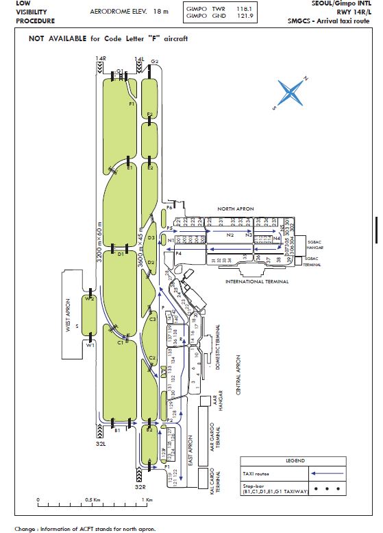
4 CAT II/III Operations
Gimpo International Airport RWY 14R has ILS CAT II Ib equipments.
Low visibility Procedures are established for operation in a visibility of less than RVR 550 m or a cloud ceiling of less than 60 m (200 ft).
-
Low visibility operations will be initiated by broadcasting "ATC LOW VISIBILITY PROCEDURES ARE IN OPERATION" via ATIS and/or appropriate radio frequencies.
-
Low visibility operations will be terminated by deleting the above mentioned message from ATIS and/or broadcasting "ATC LOW VISIBILITY OPERATIONS ARE TERMINATED" via appropriate frequencies.
-
Approval for CAT II/III Operations
-
Aircraft operators and pilots who wish to conduct ILS CAT II/III operations at Gimpo International Airport shall conform with certain requirements. Details of these requirements are published in Aviation Safety Act, Article 67 and its Enforcement regulations Article 189, which are available from :
Flight Operations Division
Seoul Regional Aviation Administration
47, Gonghang-ro 424 beon-gil, Jung-gu, Incheon,
400-718, Republic of Korea
Tel : 82-32-740-2154, 5
Fax : 82-32-740-2159
-
Foreign operators may obtain the approval from Administrator of Seoul Regional Aviation Administration by providing the following information to Administrator of Seoul Regional Aviation Administration.
1) Aircraft type and register number;
2) The Category II/III minima under which they intend to operate; and
3) A copy of the category II/III certification issued by their own category authority.
-
-
Meteorological reports preclude ILS CAT I operations;
-
Low Visibility Procedures are in operation;
-
There is any unserviceability in a promulgated facility so that they may amend their minima.
General Special procedures and ground safeguards
Special procedures and ground safeguards will be applied during CAT II/III operations to protect the aircraft from operating in low visibility and to avoid interference with the ILS signals in accordance with the provisions of ICAO Doc. 9365 - Manual of All Weather Operations, and the provisions of the Enforcement Regulations of Aviation Act, Article 5 of 186.
-
During Low visibility operations, taxiway centerline lights will be used in conjunction with the stop bar lights as follows :
-
If the stop bar lights are turned on, the centerline lights beyond the stop bar will be turned off.
-
If the stop bar lights are turned off, the centerline lights beyond the stop bar will be turned on.
-
-
Arriving Aircraft
-
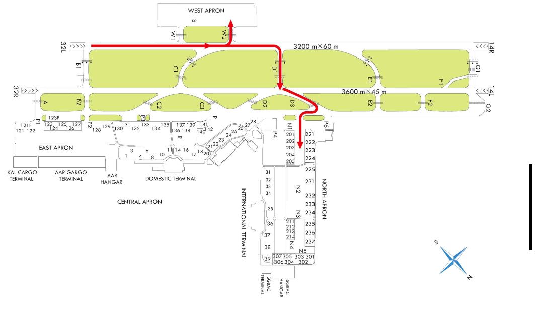
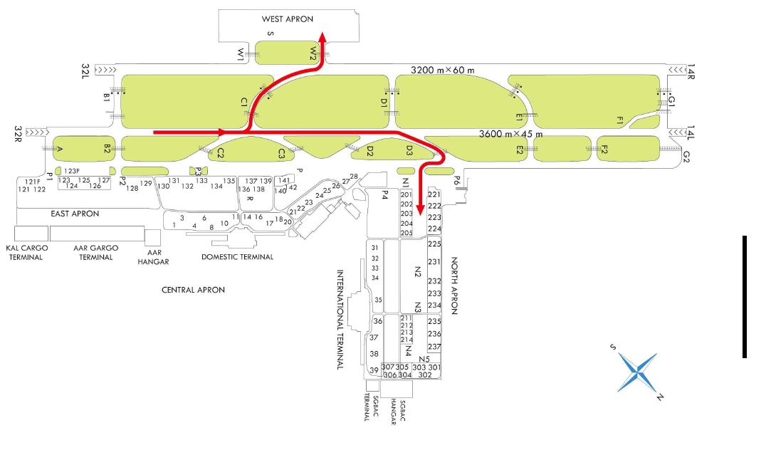
Aircraft shall vacate the runway via the designated exit taxiways as follows:
RWY 14R - B1, B2, C1, C2, P (Refer to RKSS AD 2-15)
-
14R/32L runway exits have taxiway center-line lead off lights that are color coded (green/yellow) to indicate the portion of the taxiway that is within the ILS sensitive area.
-
Pilots are required to make a 'runway vacated' call, when entire aircraft has cleared the ILS critical sensitive areas
-
-
Departing Aircraft
Departing aircraft shall normally enter the runway via the designated taxiways as follows :
RWY 14R - P, G2, G1
RWY 32L - P, B2, B1
Refer to RKSS AD 2-18, 2-19
-
Follow-me car service
-
Follow-me service is available to arriving aircraft using RWY 32L/14R when crossing RWY 32R/14L.
Pilot should make the request to Gimpo Control.
-
Aircraft shall monitor the Gimpo Ground Control frequencies during taxiing.
-
Pilots may carry out the practice of ILS CAT II approach at any time with a prior approval from ATC, but the full safeguarding ground procedures shall not be applied and pilots should anticipate the possibility of ILS signal interference.
5 The standard taxi routes for the fixed wing aircraft which has less than 2 engines :
-
Departure
1) RWY 14L/R
Remark : When reaching safety altitude, the departing aircraft shall make a right turn
before reaching the residential area for noise abatement.
2) RWY 32L/R
-
Arrival
1) RWY 14R
2) RWY 32L
3) RWY 32R

RKSS AD 2.21 NOISE ABATEMENT PROCEDURES
1 Night Flight Restriction (Curfew) for noise abatement
All take-off and landing are restricted from 1400 UTC to 2100 UTC (for flight with the purpose of training, take-off is restricted from 0900 UTC to 2100 UTC, landing is restricted from 1100 UTC to 2100UTC), except in the following;
-
Aircraft in emergency condition.
-
Aircraft which transports the patient who needs emergency medical assistance.
-
Aircraft which needs to take off or land Gimpo airport for evacuation from typhoon or heavy snow.
-
Aircraft engaged in search and rescue operation.
-
Aircraft used for national purposes designated by the relevant authorities.
2 Aircraft Operating Procedures (except helicopter)
All departing aircraft should apply ICAO PANS-OPS (Doc 8168) Volume I Noise Abatement Take-off Climb Procedure as follows;
-
Noise Abatement Department Procedure ONE (NADP ONE)
- Thrust reduction at 1 000 FT or 1 500 FT above aerodrome elevation recommended.
-
Delayed Flap Setting Procedures
All arriving aircraft shall apply delayed flap approach procedure as follows;
-
When runway 14 in use :
- After intercepting LOC, lower gear.
- Maintain intermediate flap until FAF.
※ Refer to AD 2.22.1.2 SPEED CONTROL
- At FAF, set flaps for landing and establish final approach speed.
-
When runway 32 in use :
- After 7 ILS/DME(8 DME from KIP), lower gear.
- Maintain intermediate flap until FAF.
※ Refer to AD 2.22.1.2 Speed Control.
- At FAF, set flaps for landing and establish final approach speed.
-
-
Aircraft unable to comply with this procedure for any reason should inform ATC.
-
Exception
Procedures described in the provisions 1 and 2 need not be complied with, for aircraft who have passed the IAF (for RWY 32) or intercepted the LOC(for RWY 14) in adverse operating conditions such as the following :
-
If the runway is not clear and dry, i.e. it is adversely affected by snow, slush, ice, water or other substances;
-
In conditions when the ceiling is lower than 500 FT above AGL, or when the horizontal visibility is less than 1900 M;
-
When the cross-wind component, including gusts, exceeds 15 KT;
-
When the tail-wind component, including gusts, exceeds 5 KT;
-
When wind shear has been reported or forecasted.
-
-
When RWY 14 in use
-
Take-off : RWY 14L
-
Landing : RWY 14R
-
-
RWY 32 Operation Hours
Operation Hours
For Departure
For Landing
2100-2359
32R
32L
0000-0259
32L
32R
0300-0559
32R
32L
0600-0859
32L
32R
0900-1159
32R
32L
1200-1459
32L
32R
* These operation hours can be changed depending on weather condition and traffic situation
-
Intersection take-off is not available on all runways except in an unavoidable case for traffic flow or other reasons.
RKSS AD 2.22 FLIGHT PROCEDURES
1 IFR
The following procedures are established for all turbo jet departures from Gimpo International Airport :
-
Aircraft shall contact Clearance Delivery and provide the following information 5 minutes prior to startup or push-back.
-
Aircraft Identification
-
Type of aircraft
-
Destination
-
Proposed flight level
-
Gate or stand number
-
ATIS code
-
-
If aircraft fails to push back or taxi within 15 minutes after receipt of ATC clearance, pilot should notify ATC except when :
-
Start-up or push-back is delayed due to traffic on the ground, or
-
Aircraft departure is restricted by means of release time or the same altitude/route separation
-
-
All aircraft shall not exceed 250 kt IAS below 10 000 ft in SEOUL TMA, unless otherwise authorized by ATC. If unable to comply with this speed restriction, state minimum speed acceptable to ATC.
-
ATC will use “NO ATC SPEED RESTRICTIONS” RTF phraseology to remove MAX 250 kt IAS below 10 000 ft.
-
speed control under radar vector :
-
When arriving traffic is being sequenced under radar direction, ATC typically will apply the following speed control :
-
Initial approach phase : 210 kt IAS
-
base leg/HDG to final approach : 180 kt IAS
-
When established on final approach : 180 kt to 160 kt IAS
-
Thereafter to 7.5 DME : 160 kt IAS
-
-
These speed restrictions are essential for smooth and safe operations at high traffic loads. If an aircraft does not comply with these speed instructions, the aircraft may have to be excluded from the planned approach sequence.
-
When ATC use “RESUME NORMAL SPEED“ RTF phraseology, it means that the previously issued speed restriction by ATC is cancelled and a pilot can resume an aircraft’s preferred speed. Pilot shall note that it does not mean the removal of MAX 250 kt IAS with in SEOUL TMA.
-
Fuel Dumping Area is established within SEOUL TMA as follows.
-
AREA : A circle with a radius of 5 NM centered on R 264 NCN/D22, R 278 SEL/D45.
-
ALTITUDE : At or above 6 000 FT.
-
Area/altitude may be changed by pilot request, traffic condition or any other safety reason.
Visual Approach may be initiated by ATC or approved upon pilot request on traffic permitting basis when;
-
Ceiling : at or above 1 000 ft (reported weather by the airport)
-
Visibility : not less than 5 KM (3 SM)
-
Circuit : west pattern only
-
Pilot shall note that adherence to SID / STAR level restrictions are critical for aircraft separation in SEOUL TMA. For ATC separation, pilots are strongly encouraged to check whether he or she can comply with level restrictions of SID(before airborne) / STAR(before passing subsequent waypoint) or not.
-
If unable to comply with any restrictions depicted on SID or STAR, pilot shall notify ATC as early as possible.
-
To eliminate safety risk due to a mismatch between ATC and pilot expectations, ATC will provide aircraft with explicit indications with regard to what is expected in terms of speed and level at all times using “CANCEL (LEVEL/SPEED) RESTRICTIONS” or “COMPLY WITH (LEVEL/SPEED) RESTRICTIONS” RTF phraseology.
-
When instructed to "CONTACT", pilot shall Squawk IDENT and report callsign only on initial contact.
-
When instructed to "MONITOR or STAND BY FOR", pilot shall Squawk IDENT and keep silent until ATC initiate call.
2 VFR
-
VFR Weather minima
-
Ground Visibility : Not less than 5 KM (3 SM)
-
Ceiling : at or above 450 M (1 500 FT)
※ School and Training Flights
Ceiling : at or above 610 m(2 000 ft)
-
-
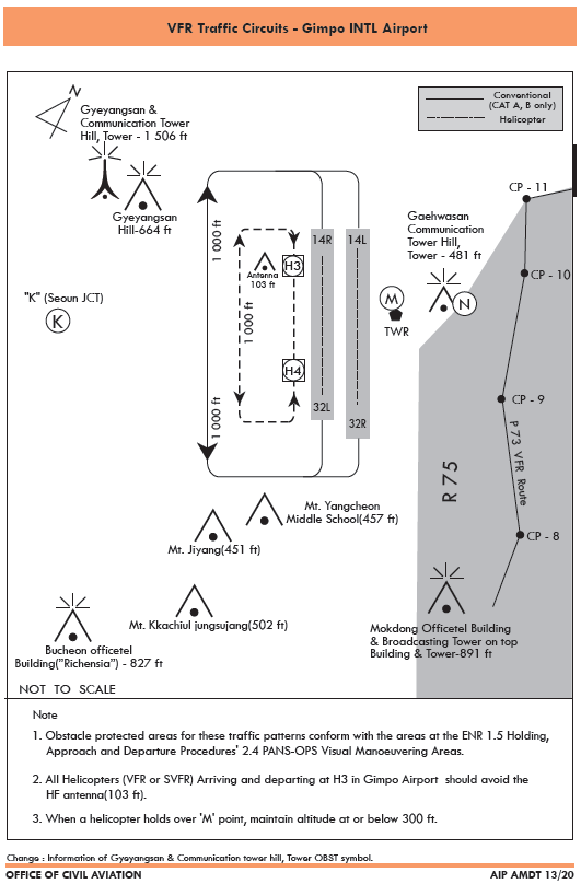
VFR Traffic Circuit : Refer to Page RKSS AD 2-29
-
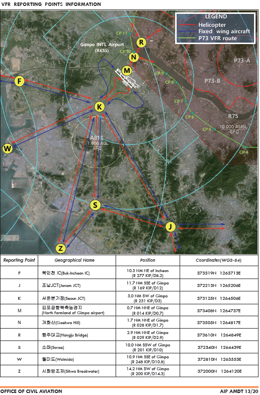
VFR Reporting point : Refer to Page RKSS AD 2-30
-
VFR Circuit Altitude
-
Helicopter : 1 000 FT
-
Conventional : 1 000 FT
-
-
VFR Flight procedure
-
VFR aircraft shall maintain two way radio communication and get permission prior to entering Class B airspace from Seoul Approach Control except
1) when landing and departing within Gimpo Control Zone via VFR reporting points.
2) for transiting through Gimpo Control Zone.
-
VFR Aircraft shall pass "K" at or above 2 000 FT unless otherwise when cleared or instructed by ATC or when necessary for safety or hazardous in-flight weather condition.
-
Aircraft is required to use traffic circuit for each runway in use.
-
"F"and "W"are radio transfer points between Gimpo and Incheon control zone.
-
As practical as possible, pilot should avoid congested areas, hospitals and schools.
-
-
Fixed Wing VFR Procedures
Departure
-
After departing from RWY 14, pass the RWY end and reach the safe altitude, then fly the following routes;
1) For SOUTH bound: Turn right then proceed to K for the next VFR reporting point or for further ATC instructions. Cross K at or above 2 000 FT.
2) For NORTH bound: Turn right then proceed to K for further ATC instructions. Pass K at or above 2 000 FT.
-
After departing from RWY 32, pass the RWY end and reach the safe altitude, then fly the following routes;
1) For SOUTH bound: After take-off, turn left then proceed to K for the next VFR reporting point or for further ATC instructions. Cross K at or above 2 000 FT.
2) For NORTHEAST bound: After take-off, maintain RWY heading then turn right when ATC gives instruction.
Arrival
-
Inbound from SOUTH: Proceed to K via a VFR reporting point or as instructed by ATC, then fly the following route. Cross K at or above 3 000 FT;
1) When RWY 14 in use: Enter into the right-hand pattern at 1 000 FT then land on RWY 14L/R as instructed by ATC
2) When RWY 32 in use: Enter into the left-hand pattern at 1 000 FT then land on RWY 32L/R as instructed by ATC
-
Inbound from NORTH: Enter into N or R then climb to 3 000 FT as instructed by ATC. Proceed to K via KIP.
1) When RWY 14 in use: Enter into the right-hand pattern at 1 000 FT then land on RWY 14L/R as instructed by ATC
2) When RWY 32 in use: Enter into the left-hand pattern at 1 000 FT then land on RWY 32L/R as instructed by ATC
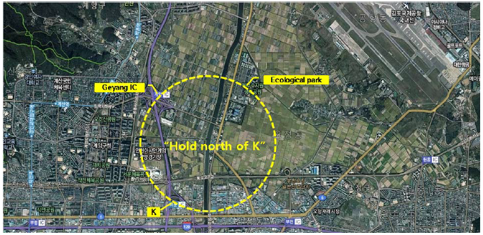
Holding
-
When ATC clears "Hold north of K", pilots shall fly connecting "K" - Geyang IC (R 256 KIP/D2.2, 373238N 1264455E) - Bucheon city northern water resources ecological park (R 255 KIP/D1.5, 373239N 1264603E)maintaining at or above 2 000 ft as instructed by ATC.
※ CAUTION : Use caution not to fly beyond the line of 1.5NM west of RWY 32L/14R in order to protect the VFR traffic circuits.
-
This holding procedure may only be permitted when
1) Day time
2) VMC
3) Aircraft type: C-172
※ When radio communication failure, all VFR flights shall follow 3.1.1 (Refer to page AD 2-27, Radio communication failure procedure)
-
-
Helicopter VFR Procedures
Departure
-
From H4 : After take-off, maintain RWY heading and reach safe altitude, then fly the following procedures;
1) For SOUTH bound : After take-off, turn right then proceed to and cross K at 2 000 FT for the next VFR reporting point or for further ATC instructions.
2) For NORTHEAST bound : After take-off, cross RWY as instructed by ATC then proceed to M then N for further ATC instructions.
-
From H3 : After take-off, maintain RWY heading and reach safe altitude, then fly the following procedures;
1) For SOUTH bound : After take-off, turn left then proceed to and cross K at 2 000 FT for the next VFR reporting point or for further ATC instructions.
2) For NORTHEAST bound : Cross RWY as instructed by ATC then proceed to M and N for further ATC instructions.
Arrival
-
Inbound from SOUTH : Proceed to K via a VFR reporting point or as instructed by ATC, then fly the following routes. Cross K at 2 500 FT;
1) When RWY 14 in use : Enter into the right-hand pattern at 1 000 FT then land on H3 as instructed by ATC
2) When RWY 32 in use : Enter into the left-hand pattern at 1 000 FT then land on H4 as instructed by ATC
* When tailwind is less than 5 knots, ATC will instruct otherwise for noise abatement.
-
Inbound from NORTHEAST : Enter into and cross N at 1 000 FT. Cross M as instructed by ATC at or below 300 FT. Cross RWY with ATC instruction then land on H3 or H4.
-
-
Special VFR flight for taking off or landing may only be permitted when
-
The ground visibility is at least 1 500 m
-
If ground visibility is not reported, the flight visibility is at least 1 500 m.
-
-
For Special VFR operations, the pilot shall :
-
get a clearance from ATC.
-
stay clear of clouds.
-
fly only within control zone as cleared by ATC.
-
maintain visual reference with surface or water.
-
maintain at least 1 500 m of flight visibility.
※ At night(between sunset and sunrise), the pilot must have an instrument rating and the aircraft must be equipped for IFR flight under Aviation Act.(Except for helicopters)
-
3 Radio communication failure procedure
-
Squawk 7600
-
Continue to fly in VMC
-
Land at nearest suitable aerodrome
-
Squawk 7600. Proceed and cross “K” at 2,000ft; and
-
Follow "Hold north of K" procedure at 2 000 ft (refer to Page AD 2-26, Holding); and
-
When able to see the light gun signal from the control tower during holding follow that instruction; or
-
When unable to see the light gun signal from the control tower continue holding, until ETA or for 10 minutes, whichever is later; then
-
Land on RWY14R/32L or H3/H4 in use as appropriate.
-
Squawk 7600
-
Maintain the last assigned speed and level, or minimum flight altitude if higher, for a period of 7 minutes following:
-
the time the transponder is set to Code 7600; or
-
the time the last assigned level or minimum flight altitude is reached;
whichever is later and thereafter adjust level and speed in accordance with the filed flight plan;
-
-
When being vectored or having been directed by ATC, proceed in the most direct manner possible to rejoin the current flight plan route no later than the next significant point, taking into consideration the applicable minimum flight altitude;
-
Squawk 7600
-
Follow the STAR issued by ATC. When being vectored or having been directed by ATC, proceed in the most direct manner possible to join the STAR no later than the next significant point. Then commence descent as filed.
-
Start approach to the assigned runway without delay.
-
If no specific runway for landing has been assigned, start approach to runway 14R or 32R without delay.
* No fly area : The aircraft shall not fly north of R 270 YJU.
4 Take-off weather Minima
| Facilities |
RWY |
3 RVR REQ |
REDL & RCLL |
REDL & RCL *** |
NIL (Day Only) REDL & RCL |
|||||
| TGS*, HIRL & RCLL |
HIRL & RCLL |
REDL & RCLL |
||||||||
| RVR / VIS** | ||||||||||
| Multi- Engine ACFT |
14R |
75 m / 300 ft |
125 m / 400 ft |
150 m / 500 ft |
200 m / 600 ft |
300 m / 1 000 ft |
400 m / 1 200 ft |
500 m / 1 600 ft |
||
| 32L |
75 m / 300 ft |
125 m / 400 ft |
150 m / 500 ft |
200 m / 600 ft |
300 m / 1 000 ft |
400 m / 1 200 ft |
500 m / 1 600 ft |
|||
| 14L |
- |
- |
- |
- |
- |
400 m / 1 200 ft |
500 m / 1 600 ft |
|||
| 32R |
- |
- |
- |
- |
- |
400 m / 1 200 ft |
500 m / 1 600 ft |
|||
Note : SIDs are designed in accordance with STANDARDS for FLIGHT PROCEDURE DESIGN.
* With certified TGS(Take-off Guidance System).
** The TDZ RVR/VIS may be assessed by the pilot.
*** For Night Operations at least REDL or RCLL and RENL are available.
5 Flight procedures construction criteria
Flight procedures are based on guidance contained in the 5th edition of ICAO Doc 8168 - Procedures for Air Navigation Services - Aircraft Operations (PANS-OPS).
RKSS AD 2.23 ADDITIONAL INFORMATION
-
Bird concentrations in the vicinity of the airport
-
Summer and Autumn
White Heron appears from July to October, which is migrant. They build nests randomly on any field around the airport. Due to the resting and feeding activity, the flock activity in the aerodrome occurs from sunrise to sunset. Careful attention is needed during landing approach and take-off.
-
Winter
Between October and March of the coming year, migrant birds (mainly wild geese and ducks) build nests on Han river downstream (24 km north from Runway 14). The flock’s main activity apt to occur around the Gul-po stream close to the runway 14R and 14L area. Some part of the flock enter into the aerodrome for resting and feeding about an hour before sunrise till sunset. The flock size of one route is approximately 1 000 individuals. Sometimes the flock flies across the middle of the runways for their group movement in the daytime. The flying height varies from 200 ft to 1 000 ft.
-
Intense activities of sedentary birds (pigeons and magpies) and seasonal activity of various migrants(wild geese, ducks, white heron and etc..) take place around the runways and the airport boundary during landing and take-off procedures.
-
Also, Aerodrome operator estimates the bird activities and hazard to inform control tower of the possible hazard. Then the tower directly warns the aircraft pilots of the hazard. Dispersal activities for the birdstrike prevention performed by the aerodrome control team include random playback of distress noise (AV-alarm and Gas canon), elimination of the wildlife hazard using firearms and environmental control such as prohibiting wide farming activity.
-
-
ATIS Telephone Service
-
Hours of operation : 2000-1400 UTC
-
ARS telephone number : +82-2-2660-2676
-
Telephone service is reference only. For the flight operation, use ATIS on the FREQ 126.4 MHz, 317.8 MHz.
-
